38
PHTM II
Installation, Operating & Service Instructions
110331-01 - 5/20
11 Domestic Water Piping
NOTICE: DHW feature on this boiler is designed
to only heat potable water (i.e. water from a well
or water utility that is suitable for drinking) having
following characteristics:
• Hardness less than 200 grains/gallons
• pH between 6 and 8
• Chlorides less than 80 PPM
Use of water not having these characteristics
could result in premature failure of DHW handling
components in this boiler and is not covered
under warranty.
DANGER
Scald Hazard.
• Under certain conditions this boiler
can deliver domestic hot water (DHW) at
temperatures in excess of DHW set point on
boiler control. A field supplied ASSE 1017 or
ASSE 1070 certified tempering valve is therefore
REQUIRED as par t of this boiler's installation.
• Select and install tempering valve in
accordance with valve manufacturer's
instructions and applicable local codes. In
absence of such codes follow Uniform Plumbing
Code (IAPMO/UPC-1). Also note additional
tempering valves may be required at fixtures
themselves.
!
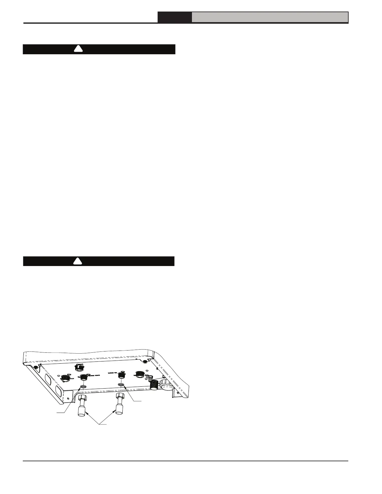
Combi connections are G1/2". Adapters to 3/4" sweat
connection are provided in miscellaneous parts car-
ton (Figure 11-1).
DHW components in this system and their functions are
as follows:
1. ASSE 1070 or ASSE 1017 listed tempering
valve (required)
Low draw rates and transitions from
heating to DHW are two examples of
conditions that can cause temperature of
water leaving boiler to significantly
exceed DHW set point. A tempering valve is
required to minimize spikes in DHW
temperature. Select and install in
accordance with valve manufacturer's
instructions and applicable codes.
2. Flow limiter
If DHW draw rate is in excess of rating in
Table 3-1, temperature of hot water may
be too low for comfortable use. Internal, 6 GPM
(23 L/min), flow limiter is factory installed,
but an additional flow limiter may be required.
Select one having a flow rating approximately
equal to that shown in Table 3-1 at desired
temperature rise.
3. DHW pressure relief valve
Limits pressure in DHW piping. Use a valve
designed for DHW service such as watts #3L
or #53L. Select a valve with a pressure setting
less than or equal to 145 psi (1,000 kPa). Pipe
discharge to safe location using same
size as discharge connection to valve.
4. Drain valve
Permits plate heat exchanger to be periodically
back flushed to remove sediment.
5. Globe or ball valves
Used to isolate DHW piping during back
flushing and other servicing. In addition, valve may
be used to limit DHW flow if necessary.
6. Expansion tank
If back flow preventer or check valve is
installed upstream of cold connection, thermal
expansion tank will prevent build-up of
pressure in DHW piping. Use an expansion
tank designed for use in potable water
service.
7. Buffer tank (Optional)
When recirculation line is installed as shown
in Figure 11-2, a small (2-6 gal) potable water
storage tank may be installed as shown. This
will reduce burner cycling during very small
DHW demands and also help minimize
temperature fluctuations. An unpowered
storage electric water heater is ideal for this
application.
Gasket
Gasket
DHW Connector
(Fits 3/4" Female Socket Elbow)
Figure 11-1: DHW Connections
CAUTION
Component Damage.
• Internal components near Hot and Cold
connections can be damaged by excessive
heat during soldering. Use precautions to limit
heat exposure.
• Failure to do so could cause internal leaks
resulting in damage to boiler.
!
NOTICE: Elbows pointed toward back of boiler
are recommended to start DHW piping.