37110331-01 - 5/20
PHTM II
Installation, Operating & Service Instructions
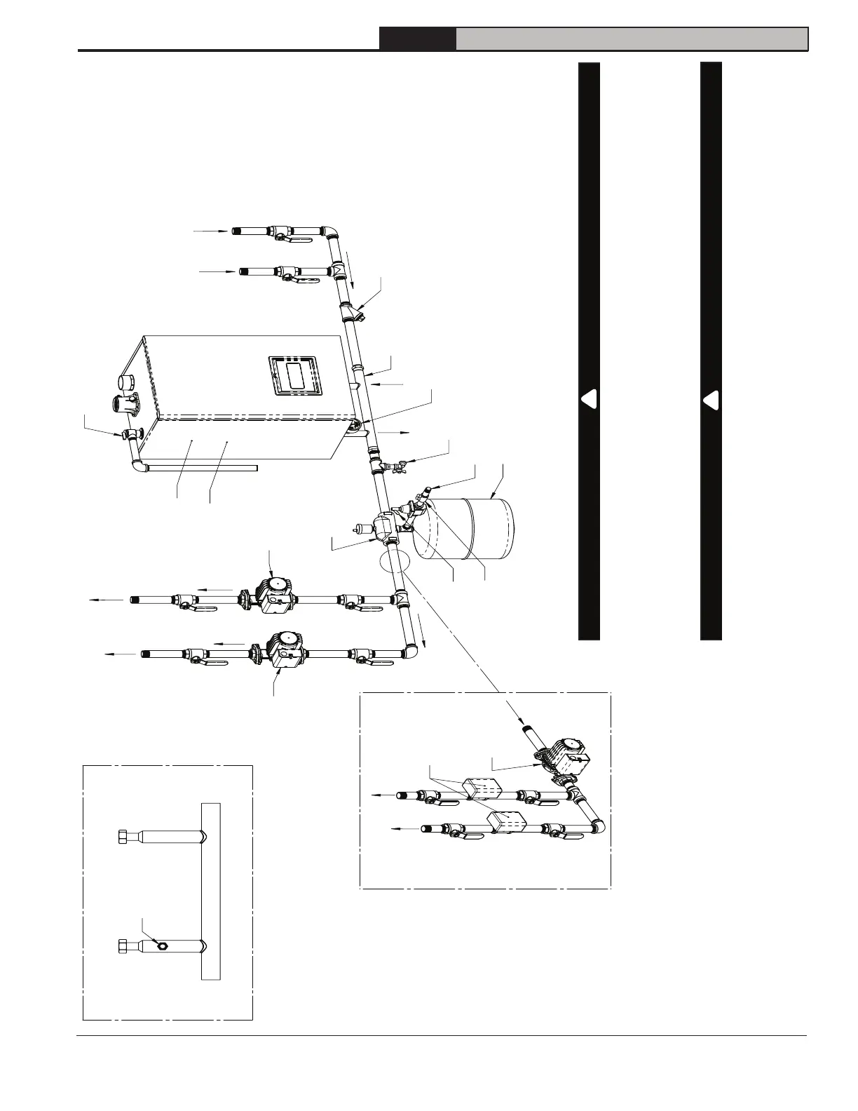
10 Heating System Piping (continued)
From System
To System
Temperature &
Pressure Gauge*
Drain Valve*
Cold Water Fill
Air Separator
& Air Vent
Expansion Tank
Low Loss Header*
Fill Valve
Backflow
Preventer
Safety Relief Valve*
Wye strainer or dirt and
magnetic filter
(highly recommended)
System Pump
w/ Integral Flow
Check Valve
System Pump
w/ Integral Flow
Check Valve
Manual Air Vent*
(inside boiler)
Boiler Pump*
(inside boiler)
* Supplied with boiler
Low Loss Header
Boiler Supply Connection
(G 3/4")
Boiler Return Connection
(G 3/4")
T&P Gauge
(1/4" NPT)
System
Return
(1-1/4" sweat)
Heating
System
Pump
To System
Optional Zone Valve
Controlled System
System Zone
Valves
System
Supply
(1-1/4" sweat)
NOTICE: Domestic water piping omitted for clarity.
NOTICE: Installer is responsible for piping configurations to provide proper flow rates and
meet local codes.
CAUTION
Burn Hazard. Property Damage.
Under some conditions this boiler can deliver water to heating system that is
significantly higher than boiler setpoint. Where such overheat could cause personal
injury or property damage (i.e. low temperature radiant floor zones), protect system
from excessive temperatures using tempering valves or other means.
CAUTION
Component Damage.
Excessive heat from soldering could damage gaskets at connection between low loss
header and boiler. Solder connections to low loss header before installing gaskets.
!
!
Figure 10-2: Heating System Piping