36
PHTM II
Installation, Operating & Service Instructions
110331-01 - 5/20
10 Heating System Piping (continued)
5. Automatic air vent (required)
A. Factory installed air vent is included on boiler
heat exchanger, to vent heat exchanger. A
system air vent is also required.
B. Manual air vents will usually be required in
other parts of the system to remove air during
initial fill.
6. Manual reset high limit (required by some codes
i.e. ASME CSD-1)
A. Install high limit in boiler supply piping just
above boiler with no intervening valves.
B. Set manual reset high limit to 200°F. Wire
limit to "external limit" terminal on low voltage
connection board per Section 13 Field Wiring.
7. Isolation valves are useful when boiler must be
drained, as they will eliminate having to drain and
refill entire system.
8. Strainer (recommended)
A. Install a Y strainer, or dirt/magnetic filter
strainer to prevent any system debris from
entering boiler and fouling of water passages.
B. Note that some strainers have a significant
pressure drop, which may impact ability of
system pump to obtain required flow.
9. Drain valve (required)
Install drain valve as shown in Figure 10-2.
10. Low water cut-off (LWCO) (may be required by
local jurisdiction)
A. Protection of this boiler against low water and/
or inadequate flow is provided by UL353
certified flow switch built into boiler.
B. This is a water tube boiler and this flow switch
is therefore only effective way to provide
such protection.
C. Section HG614(c) of 2015 ASME Boiler and
Pressure Vessel Code recognizes use of a
listed flow switch in lieu of LWCO on water
tube boilers.
D. In event a local jurisdiction insists upon
installation of LWCO with this boiler, refer
to Section 13 Field Wiring and LWCO
manufacturer's instructions for proper wiring.
• Auto reset LWCO: 105591-01
• Manual reset LWCO: 108182-01
E. Install LWCO in supply piping at point
prescribed by the local jurisdiction (generally
at a point above boiler, in common header
piping).
F. If probe type LWCO is used, be certain that it
is located at a point in piping from which air
can escape to an automatic air vent.
G. Generally, this means there should be no
down-turns in piping between LWCO
and point where automatic air vent is
installed.
H. Failure to do this may result in nuisance boiler
shut-down due to small amounts of air
trapped around probe.
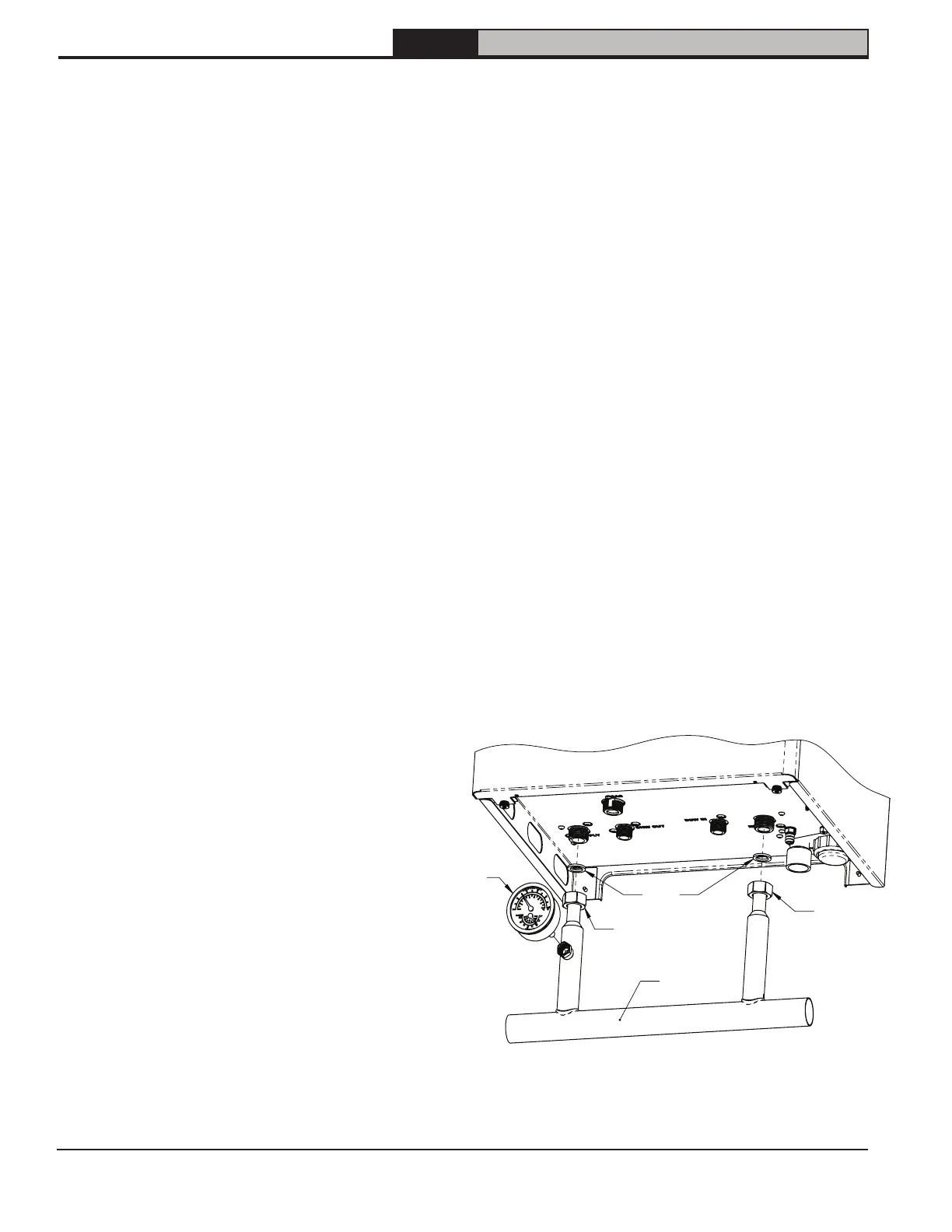
11. Low Loss Header (supplied with this boiler)
provides instant primary-secondary
connection.
Boiler Supply
Connection
(G 3/4")
Boiler Return
Connection
(G 3/4")
System
Return
(1-1/4" sweat)
System
Supply
(1-1/4" sweat)
Low Loss
Header
Gaskets
T/P
Gauge
(1/4" NPT)
Figure 10-1: Low Loss Header Connections