67110331-01 - 5/20
PHTM II
Installation, Operating & Service Instructions
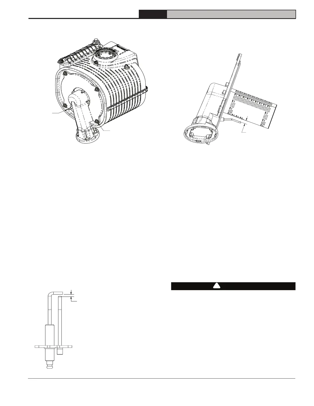
Figure 18-1: Ignitor/flame sensor location
Burner Door Mounting
Nuts (4X)
Ignitor/Flame
Sensor
18 Service and Maintenance (continued)
4. Inspect target wall and burner door insulation.
If either shows signs of damage, it must be
replaced.
5. Inspect burner door seal.
Look for signs of embrittlement or deterioration.
Replace if needed.
6. Inspect burner.
Look for heat damage or other deterioration. Use
a nonmetallic brush or source of compressed air
to clean off dust or debris from ports.
7. Inspect ignitor/flame sensor.
A. Clean off any deposits found with steel wool.
Do not use sand paper or Emory cloth for this
cleaning.
B. Inspect ceramic portion for cracks and
replace if they are found.
C. Verify ignitor/flame sensor spark gap is within
range shown in Figure 18-2.
Figure 18-2: Ignitor/flame sensor spark gap
.16" (4mm) - .19" (5mm) Gap
D. Verify gap between ignitor/flame sensor and
burner is within range shown in Figure 18-3.
WARNING
Asphyxiation Hazard.
Do not operate boiler without condensate trap
ball and ball support in place. Doing so could
cause products of combustion and or carbon
monoxide to enter building resulting in severe
personal injury, death or substantial property
damage.
!
Figure 18-3: Ignitor/flame sensor to burner gap
8. Inspect blower gas valve assembly.
A. Look for dust, lint, or other debris that may
have been drawn into this assembly.
Excessive deposits may be vacuumed out.
B. Inspect all rubber and plastic components
on blower/gas valve assembly, looking for
deterioration. Replace blower and/or gas
valve if deterioration is found.
9. Inspect and clean condensate trap.
A. Place bucket under condensate clean out cap
on bottom of boiler (Figure 18-4) to catch
water in trap as well as ball and support.
B. Unscrew cap, being careful not to lose ball or
ball support.
C. Flush any debris found in trap with water - do
not use other cleaning agents. Reassemble
trap as shown in Figure 18-4.
.32" (8mm) - .52" (13mm) Gap
.32" (8mm) - .52" (13mm)
Gap
.16" (4mm) - .19" (5 mm) Gap