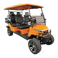
This document provides operating instructions and specifications for the Model D Golf Cart, an environment-friendly passenger vehicle designed for golf courses, resorts, villa areas, garden hotels, and tourist attractions. It emphasizes excellent performance, novel appearance, luxurious and exquisite interior decoration, and comfortable and safe driving.
Function Description
The Model D Golf Cart is an electric passenger vehicle primarily used for transportation in various recreational and leisure settings. Its core function is to provide an efficient and comfortable means of transport while being environmentally friendly.
Important Technical Specifications
The Model D Golf Cart comes in several models, including WH2020K, WH2020KSZ, WH2020A, WH2020ASZ, WH2040K, WH2040KSZ, WH2040A, WH2040ASZ, WH2060K, and WH2060KSZ, offering 2, 4, or 6 seats.
Key specifications across these models include:
- Overall Dimensions (mm):
- Length: Ranging from 2390 mm (2-seater) to 4640 mm (6-seater).
- Width: Ranging from 1215 mm to 1340 mm.
- Height: Ranging from 1880 mm to 2060 mm.
- Whole Machine Mass (kg): Ranging from 450 kg (WH2020K) to 640 kg (WH2060KSZ).
- Endurance Mileage (km): Most models offer 80 km or 70 km, with some 60 km.
- Maximum Speed (km/h): 25 km/h for 2-seater and 4-seater models, and 20 km/h for 6-seater models.
- Minimum Turning Radius of Outer Wheels (mm): Ranging from 3100 mm (2-seater) to 5200 mm (6-seater).
- Maximum Gradeability: 20% for 2-seater models, 20% or 15% for 4-seater models, and 15% for 6-seater models.
- Minimum Ground Clearance (mm): 120 mm or 200 mm depending on the model.
The vehicle adheres to the Q-321088TCD 011 202 (Whanlong Enterprise Standard).
Usage Features
The Model D Golf Cart features a user-friendly control mechanism:
- Power Lock: The vehicle is started by turning a key forward in the power lock. To shut down and remove the key, the key must be turned backward.
- Front and Rear Gear Switch: This toggle switch controls forward, reverse, and parking gears. Upward is forward, downward is reverse (accompanied by a buzzer alarm), and the middle position is parking. It is crucial to stop the vehicle and set the switch to the middle parking gear for 2 seconds before switching between forward and reverse to prevent damage and ensure safety.
- Accelerator Pedal: After selecting a gear and releasing the brake, the vehicle starts by slowly pressing the accelerator pedal. Users are cautioned against slamming the accelerator pedal.
- Brake Pedal: To slow down or stop, the right foot is moved to the brake pedal and gently pressed. Emergency braking should be avoided.
- Parking Brake Handle: Used for parking the vehicle.
- Steering Wheel: Controls the driving direction.
- Combination Instrument (Dashboard): Displays vehicle status information such as capacity, speed, mileage, and light signals. It includes a Display LCD, power lock, USB port, 12V power, clock, and hazard alarm switch.
- Combination Switch:
- Turn Signal Lamp: Lever forward for left turn signal, backward for right turn signal.
- Low Beam: Turning the front half end of the lever forward for two gears activates the low beam. Turning it backward turns it off.
- High Beam: Lifting the lever (towards the steering wheel surface) activates the high beam. Releasing it resets the lever and turns off the high beam. To achieve permanent high beam, the low beam must be turned on first, then the lever lifted.
- Horn: A button at the head end of the lever.
Operating Procedures:
- Switch on the power lock.
- Press the forward and backward rocker switch to the desired gear (forward or backward) and ensure it's in place.
- Release the parking brake.
- Press the accelerator pedal at a constant speed to start the vehicle.
- Safety Note: The forward and backward switch must be in neutral when opening the power lock, otherwise the vehicle will not drive. If the accelerator is pressed before the power lock is opened, the pedal must be released and pressed again for the vehicle to drive.
Codes of Safety Practice:
- The vehicle is an off-road vehicle and should not be driven on highways.
- Avoid overloading to prevent reduced brake performance.
- Only qualified personnel are allowed to drive.
- Drive within the approved slope range.
- Familiarize with all operations before driving and strictly follow procedures.
Maintenance Features
Maintenance is crucial for the driving performance and service life of the electric vehicle.
Battery System Maintenance (Lithium-ion power battery by Ganfeng):
- Temperature Requirements:
- Operating: -20°C to 50°C
- Storage: -30°C to 60°C
- Optimum Charge/Discharge: 25°C to 50°C
- Installation: Ensure the power switch is off. Install with insulation gloves. Properly connect discharge and communication ports. Turn on the battery power switch after confirmation.
- Check Before Driving:
- Confirm the emergency stop switch is closed.
- Observe the instrument panel for normal battery status and no alarm messages.
- Recommended to start with a full battery (SOC > 50%).
- If SOC < 30%, charge to at least 50% before running.
- Normal Operation:
- Charge immediately if battery level is below 30%. Use after full charge is recommended.
- Perform full power work at least once every two weeks.
- Battery maintenance every two months (refer to section 1.8 for specific methods, not provided in this excerpt).
- Transportation: Avoid violent shaking, large external impacts, throwing, rolling, inverting, and extrusion. Prevent rain. Ensure battery/pack is not loaded, charging device is disconnected, and no charge/discharge occurs.
- Power-on/Power-off:
- Discharge Power On: Turn key to ON, BMS powers on, battery system self-checks (no fault), then discharge relay closes. If self-test fails or serious fault, discharge relay disconnects and fault is reported.
- Discharge Power Off: Turn key to off, BMS powers off, or serious discharge fault, discharge relay disconnects.
- Charging Steps and Precautions:
- Key switch of the vehicle to be charged must be closed (vehicle not charged).
- Use matching lithium charging equipment.
- Remove charging gun head, check for foreign matter in ports, and ensure terminals are not damaged.
- Push power switch on charging device (power indicator lights up).
- Use the manufacturer's designated charger.
- Charge in a safe environment (avoid liquids and fire).
- Charging equipment should have necessary fire extinguishing devices nearby.
- Confirm no dust/foreign matter in charging gun/socket before charging.
Motor Maintenance:
- DC Motor Faults and Causes:
- Incorrect brush pressure: All copper sheets blackened.
- Short circuit/poor welding/open circuit in commutator segment: Commutator segments blackened in sets.
- Displaced/not smooth/round commutator center line: Commutator segments blackened with no certain rule.
- Worn/discolored/broken brushes: Large gap between brush and brush box, poor contact between brush and soft wire, small soft wire cross-sectional area, protruding mica plate, poor brush grinding/pressure, wrong brush grade, stuck brush, loose/vibrating brush holder, incorrect magnetic pole arrangement.
- Overloaded motor, unclean/not smooth/round commutator, protruding mica plate, poor brush grinding/pressure, wrong brush grade, stuck brush, loose/vibrating brush holder, incorrect magnetic pole arrangement: Big spark.
- Large brush spark, poor contact between brush and soft wire, small soft wire cross-sectional area: Brushes and brush discrimination lines are heated.
- Not smooth commutator surface: Brushes have noise.
- Note: Adjustment/replacement of carbon brushes and trimming of commutators require professionals.
- AC Motor Faults and Causes:
- Motor bearing damage: Abnormal noise of motor.
Electronic Control Gear Maintenance:
- The electronic control gear uses original imported products and high-frequency MOS technology for smooth, silent, efficient, and energy-saving vehicle speed, torque, and brake control.
- Runaway Prevention: If the controller detects a pedal input signal > 20% at start, it triggers the HPD protection function and prohibits output.
- Self-inspection/Diagnosis: Microprocessor performs self-inspection on power-on and continuous diagnosis during operation. Faults immediately stop output to protect operator and vehicle.
- Temperature Monitoring: AC controller has temperature monitoring and protection to prevent motor damage from high temperatures.
- Regular Maintenance (every three months):
- Check contactor contacts for good contact, adhesion, open circuit, sundries, ablation, and mechanical sticking.
- Check microswitch in accelerator for good on-off performance.
- Check direction switch for good on-off performance (CVT vehicle).
- Check connections between motor, battery pack, and controller unit (with power off).
- Keep electric control, motor, and battery pack clean. Do not flush electrical components with water; use brush or high-pressure gas for dust removal.
- Fault Characteristics and Possible Causes:
- Vehicle cannot start: Controller no power, signal not transmitted, contactor contact bonded, damaged motor/controller, wrong/damaged motor encoder phase sequence, motor/controller in temperature protection, electromagnetic brake locked.
- Vehicle only moves forward/backward: Damaged direction switch/disconnected line (CVT), loose insert on reverse contactor (CVT), damaged reverse contactor (CVT).
- Maximum speed slows down: Battery low, hand brake not released/brake shoes not reset, faulty accelerator pedal, faulty controller, excessive load, motor/controller in temperature protection, abnormal motor encoder.
Brake Part Maintenance:
- Brake pedal stroke should not exceed 2/3 of total stroke with ~30kgf force.
- Brake pad clearance is automatically adjusted.
- Parking brake handle should stick between 5-10 ratchets with 20kgf pull, effectively locking the wheel.
- Regularly check and replace brake shoes, fill lubricating oil in brake hub bearing.
Complete Vehicle Lubrication:
- Use Like 901 automobile brake fluid (do not mix brands).
- Use 85W/90GL hypoid gear oil for gearbox and rear axle (0.8L filling).
- Lubricate steering gear box, tie rod, steering knuckle, and bearing parts with butter.
Running-in of New Vehicle:
- Period: One month or 1000 kilometers.
- Before running-in: Check oil, electrolyte, brake fluid capacity and fill if insufficient. Tires should be 205/50-10 with 200-250kPa pressure.
- Avoid driving on ring roads.
- Check and tighten connecting parts if loose.
- Control speed within 15km/h during running-in.
General Precautions:
- Ensure parking brake is fully released before driving.
- Check rear powertrain every three months, fill/replace grease.
- Check brake shoe wear every three months, adjust/replace as needed.
- Check electrical system fastening monthly, especially large current circuits (battery, motor, electric control). Correct defects and remove dust.
- Monitor electrical contacts for heating.
- When changing fuses, ensure correct rated current.
- Remove positive and negative power cables of battery pack during maintenance for safety.
- Avoid slamming/inching accelerator frequently.
- Only add distilled water to battery (no additives, mineral water, tap water).
- Drive safely: no high speed downhill, slow down when turning, remind passengers to use handrails.
- Children are forbidden to play in the vehicle; they should sit in the middle and be supervised by adults.
- Follow regular maintenance schedule (table provided in manual).
Fuse Location:
- Plug-in accessory fuses (six for DC, six for AC) are in the fuse box inside the instrument desk.
- One bayonet main fuse is on the controller mounting plate under the rear seat.
Storage:
- Store in a cool, dry, ventilated environment, protected from sun, rain, and dust when not in use for extended periods.
After-sales Service:
- Customer service hotline: 0514-80915501 (24-hour).
- Warranty: One year for the complete vehicle (excluding quick-wear parts) for non-human failures under specified conditions. Replaced parts are not returned.
- Warranty Conditions: All parts must be original and within warranty period.
- No Warranty Under: User's failure to follow instructions/improper storage, user disassembly/maintenance, natural disasters/accidents (parts damage, theft, loss).
- Quick-wear parts (bulbs, fuses, brake pads, glass products, connectors, etc.) are not covered.
- Warranty Period Determination: Valid user warranty card and purchase invoice copy are vouchers. If not available, date is calculated from product ex-factory number.