OPERATIONAL CONTROLS
Operation - 23
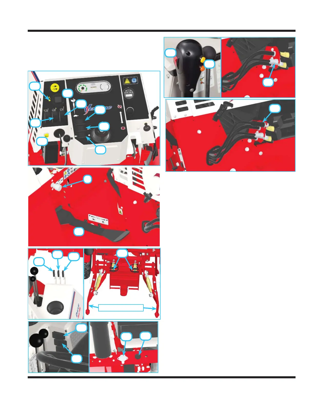
Optional Operational Control Locations
Use the following images to help identify the locations
of operational controls for optional kits. The letter next
to each control can be referenced to the list that fol-
lows these images.
AA. Work Light Switch
BB. Strobe Light Switch
CC. Slope Indicator Gauge
DD. Slope Warning Light
EE. Directional Signal Switch
FF. Hazard Flasher Switch
GG. Gas/Propane Selector Switch (4500Z only)
HH. Horn Switch
II. Front Hitch Valve
JJ. Foot Pedal
KK. 3 Point Hitch Control Handle
LL. Left Rear Auxiliary Hydraulics Handle
MM. Right Rear Auxiliary Hydraulics Handle
NN. Rear Auxiliary Hydraulic Quick Couplers
OO. Rear 12V Switch (On/Off)
PP. Rear 12V Switch (Momentary On/Off/On)
QQ. Rear 12V 4-Pin Socket
RR. Front 12V Switch (On/Off)
SS. Front 12V Switch (Momentary On/Off/On)
TT. Front 12V 4-Pin Socket
UU. Electric PTO Remote Socket
VV. Back Up Alarm
HH
AA
CC
DD
EE
FF
GG
BB
II
JJ
KK
MM
LL
3 Point Hitch Arms
NN
RR
SS
TT
UU
OO
PP
QQ
VV