OPERATIONAL CONTROLS
Operation - 26
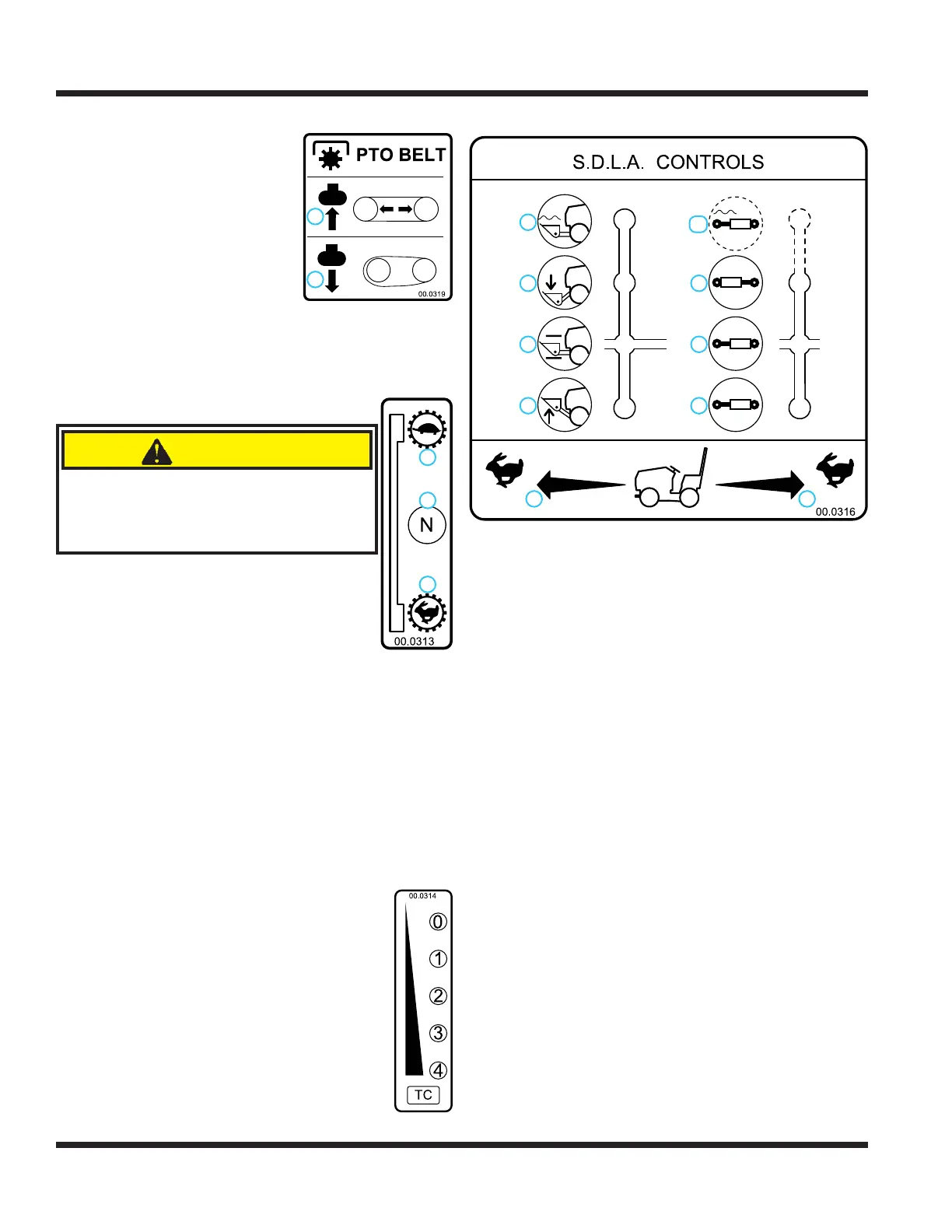
PTO Belt Tensioner Rod (N)
The PTO belt tensioner rod
applies or releases belt tension
to the attachment drive belt.
After placing the attachment
drive belt onto the PTO drive
pulley, pushing the PTO belt
tensioner rod in (1) until it locks
applies tension to the attach-
ment drive belt.
Pulling the the PTO belt ten-
sioner rod out (2) releases the
belt tension, allowing the operator to remove or install
the attachment drive belt.
High/Low Shift Lever (O)
CAUTION
Never shift while under load, while mov-
ing, or while on a slope. Always ensure
the shift lever is secured in the lock
position at the end of each shift stroke.
The high/low range shift lever shifts both the
front and rear transaxles simultaneously.
With the power unit parked on level
ground, push the shift lever forward to
select low range (1).
Move the shift lever to middle of the
shift stroke to place the transaxle gears
in neutral (2).
Pull the shift lever back toward the operator to
select high range (3).
Ensure the shift lever is secured in the lock position
at the end of each shift stroke.
Weight Transfer Traction Control Select
Lever (P)
The weight transfer system transfers weight from
the attachment to the front wheels of the
power unit. Transferring weight from the
attachment to the power unit increases the
traction control, improves hillside maneu-
verability, aids in lifting the attachment,
reduces steering effort, and lessens the
attachment resistance when in contact with
the ground.
The operator can select different transfer
rates by selecting one of the fi ve positions
from no weight transfer (0) to maximum
weight transfer (4). Set the weight transfer
to 0 when attaching or detaching any attachment.
SDLA Control Lever (Q & R)
2
1
9
8
7
6
5
4
3
10
1. Forward Direction
2. Reverse Direction
3. Lift
4. Hold
5. Lower
6. Float
7. Direction #1
8. Hold
9. Direction #2
10. Float (if equipped)
The SDLA (Speed, Direction, Lift, and Auxiliary) is
the primary control for the power unit and consists
of two levers. The primary SDLA control lever (Q)
controls the speed, direction of travel, and lift of the
hitch arms. The secondary SDLA control lever (R)
controls the auxiliary hydraulic circuit.
S - Speed: the amount of forward or backward
movement of the primary SDLA lever controls
the ground speed of the power unit.
D - Direction: the forward or backward movement of
the primary SDLA lever controls the direction of
the power unit.
L - Lift: the lift function of the primary SDLA lever has
four positions: Up, Hold, Down, and Float Lock.
“Hold” is the default position; this holds the lift
arms from moving up or down. Pulling the lever
to the left raises the hitch arms. Pushing the lever
to the right lowers the hitch arms. Float position is
attained by pushing the lever to the right until the
fl oat detent locks the lever in place.
A - Auxiliary: the left or right movement of the
secondary SDLA lever controls the functions of
attachments that require the auxiliary hydraulic
circuit. An optional fl oat kit (part # 23.0111-7) is
available for the auxiliary circuit.
1. Belt Tension Engaged
2. Belt Tension Released
2
1
2
3
1
1. Low Range
2. Neutral
3. High Range