GENERAL OPERATION
Operation - 34
To set the weight transfer, raise the front hitch to
its maximum height and move the weight transfer
select lever to the desired position.
Selecting the proper amount of weight to transfer
depends on attachments, ground conditions and oper-
ator preference. A lightweight attachment (e.g. KA160
power blower) will not go down with full weight transfer
on. With full weight transfer on, and mowing in the
fl oat position, the mower may not come down quickly
enough when going through uneven terrain. Power
unit speed or weight transfer rate must be reduced.
High/Low Range
L
CAUTION
Never shift while under load, while moving, or while
on a slope. Always ensure the shift lever is secured
in the lock position at the end of each shift stroke.
Always use low range when operating on slopes
of greater than 15 degrees.
ow range is recommended for most pulling, push-
ing, and slow travel. High range is ideal for transport
and light duty tasks.
1. Park the power unit on level ground and engage
the parking brake.
2. Move the shift lever to the desired range position.
NOTE: occasionally the engagement of the trans-
axle gears is prevented by misalignment. Moving the
steering wheel slightly to the right or left will move the
gears enough to complete the engagement.
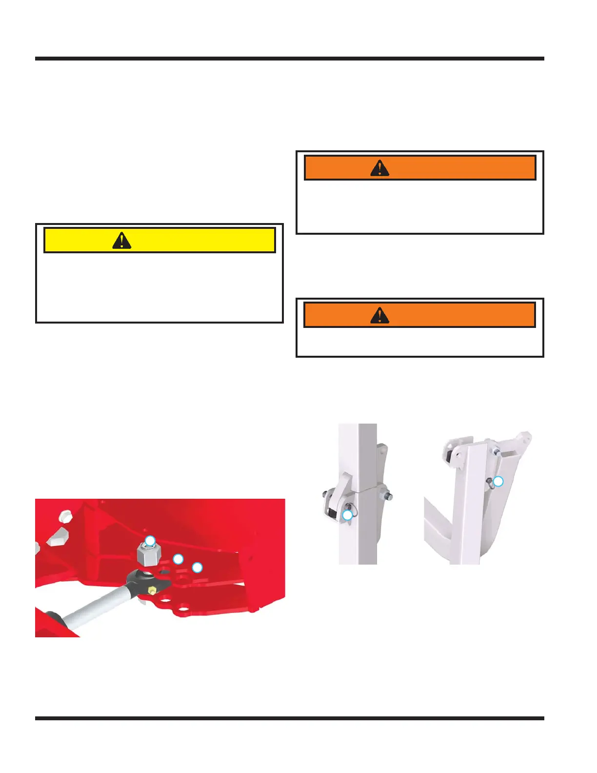
Turning Radius
The 4500 has three mounting positions for the steering
cylinder that determine the power unit’s turning radius.
1.
1
3
2
Standard position: this position is the standard
position and enables the tightest turning radius.
2. Dual wheel position: The steering cylinder must
be installed in this position when operating with
dual wheels. The resulting turning radius will be
larger than position number 1.
3. Cab and Versa-loader position: The steering
cylinder must be installed in this position when
the cab is installed or when operating the Versa-
loader. The resulting turning radius will be larger
than position number 2.
Roll-Over Protection System
WARNING
Keep the ROPS locked in the upright position and
the seat belt securely fastened during operation.
Failure to do so could result in serious injury or
loss of life.
The 4500 is equipped with a fold down ROPS that
allows the power unit to access areas of low over-
head clearance. Lower the roll bar only when abso-
lutely necessary and raise the roll bar to the upright
position as soon as clearance allows.
WARNING
Do not wear a seat belt when the roll bar has
been lowered to the down position.
To lower the roll bar:
1. Remove the pins from the right and left hinge
plates (1).
2. Fold the roll bar down and install the pins in the
hinge plates (2) to lock in place.
1. Locked Upright 2. Locked Folded Down
2
1
To raise the roll bar:
1. Remove the pins from the right and left hinge
plates (2).
2. Raise the roll bar to the upright position and install
the pins in the hinge plates (1) to lock in place.