OPERATIONAL CONTROLS
Operation - 27
Steering Wheel (S)
Turn the steering wheel to the left (counterclockwise)
to turn the power unit to the left. Turn the wheel to the
right (clockwise) to turn the power unit to the right.
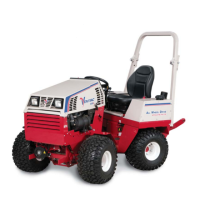
Hydraulic Cooler Fan Switch (T)
The hydraulic oil cooler fan
switch is normally set to the
automatic thermostatically
controlled position (1). This
allows the thermostat to turn
on the cooling fan when the
hydraulic fl uid reaches the set
temperature. The fan pulls air
through the right fender next
to the operator, through the oil
cooler, and discharges the air
out the back of the power unit.
The switch can be set to the
reverse position (2) to pull air
from the back of the power
unit, through the oil cooler,
and discharge the warm air next to the operator.
This feature can be used to help provide warmth for
the operator during cold weather.
Seat Slide Lever (U)
Move the seat slide lever to the left to release the
seat lock. Move the seat forward or backward to the
desired position and release the seat slide lever to
lock the seat in place.
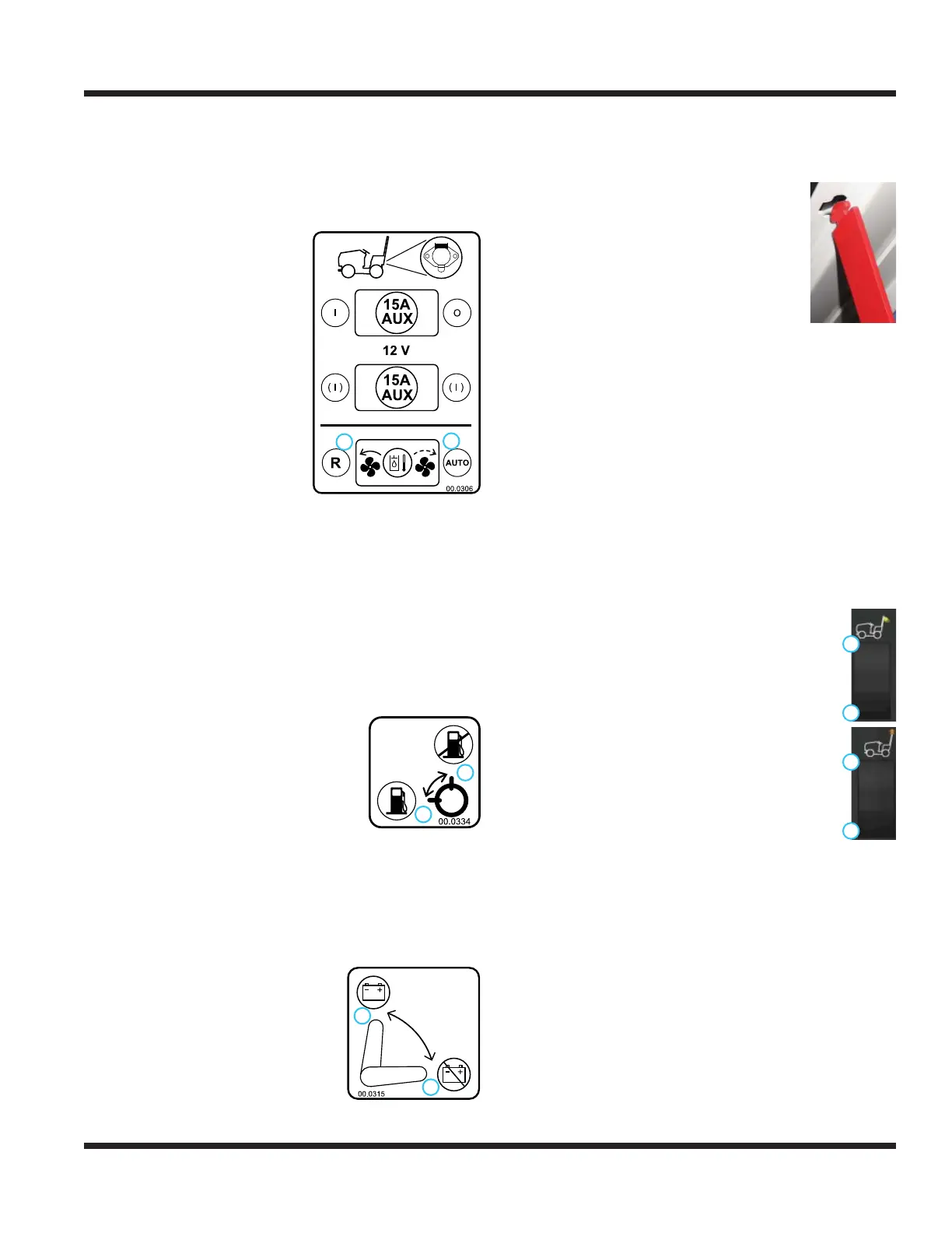
Fuel Shut-off Valve (V)
The fuel shut-off valve controls the
fl ow of fuel to the power unit engine.
Turning the valve to position 2 will
allow fuel to fl ow to the engine.
Turning the valve to position 1 shuts
off the fuel fl ow to prevent fuel leak-
age when changing fuel fi lters or
servicing the fuel system. Turn off the fuel shut-off
valve when transporting the power unit on a truck or
trailer and when parking the power unit indoors.
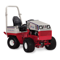
Circuit Breaker & Battery Disconnect (W)
The circuit breaker/battery dis-
connect switch controls power
to the entire electrical system.
Turning the switch to position 2
disables the electrical system,
allowing electrical components to
be serviced.
Seat Prop Plate (X)
The seat prop plate secures the seat in the fl ipped
forward position while service is performed under
the seat.
To secure, tilt the seat forward, lift up
the seat prop, and insert the end into
the wide portion of the seat plate slot.
Ensure the seat prop plate snaps into
the narrow portion of the slot to prevent
accidental release.
To release, move the seat prop plate
over into the wide portion of the seat slot and tilt the
seat forward. Lower the seat prop plate back into
the seat box and lower the seat back down to the
operating position.
Seat Latch Strap (Y)
The seat latch strap secures the seat during trans-
port of the power unit.
To secure the seat, place the tab on the end of the
seat latch strap over the seat latch pin. Install the
linch pin through the hole in seat latch pin to secure.
To release the seat so that it can be tilted forward
for service, remove the linch pin and lift the tab on
the seat latch strap off the seat latch pin.
Work Light Switch (AA)
Depressing the top (1) of the work
light switch turns on the work lights.
Depressing the bottom (2) of the switch
turns the work lights off.
Strobe Light Switch (BB)
Depressing the top (1) of the strobe
light switch turns on the strobe light.
Depressing the bottom (2) of the switch
turns the strobe light off.
Slope Indicator Gauge (CC)
The digital slope indicator gauge works with a bidi-
rectional slope meter to display the angle of a slope
in degrees. NOTE: sudden changes in speed or
direction may affect the slope value displayed.
Slope Warning Light (DD)
The slope warning light works with the slope indi-
cator system to provide a visual warning when the
slope value exceeds 20 degrees.
1
2
1. Normal (auto) Operation
2. Reverse Operation
2
1
1. Fuel Off
2. Fuel On
1
2
1. Electrical Power On
2. Electrical Power Off
2
1
1. On
2. Off
2
1
1. On
2. Off