SERVICE
Service - 53
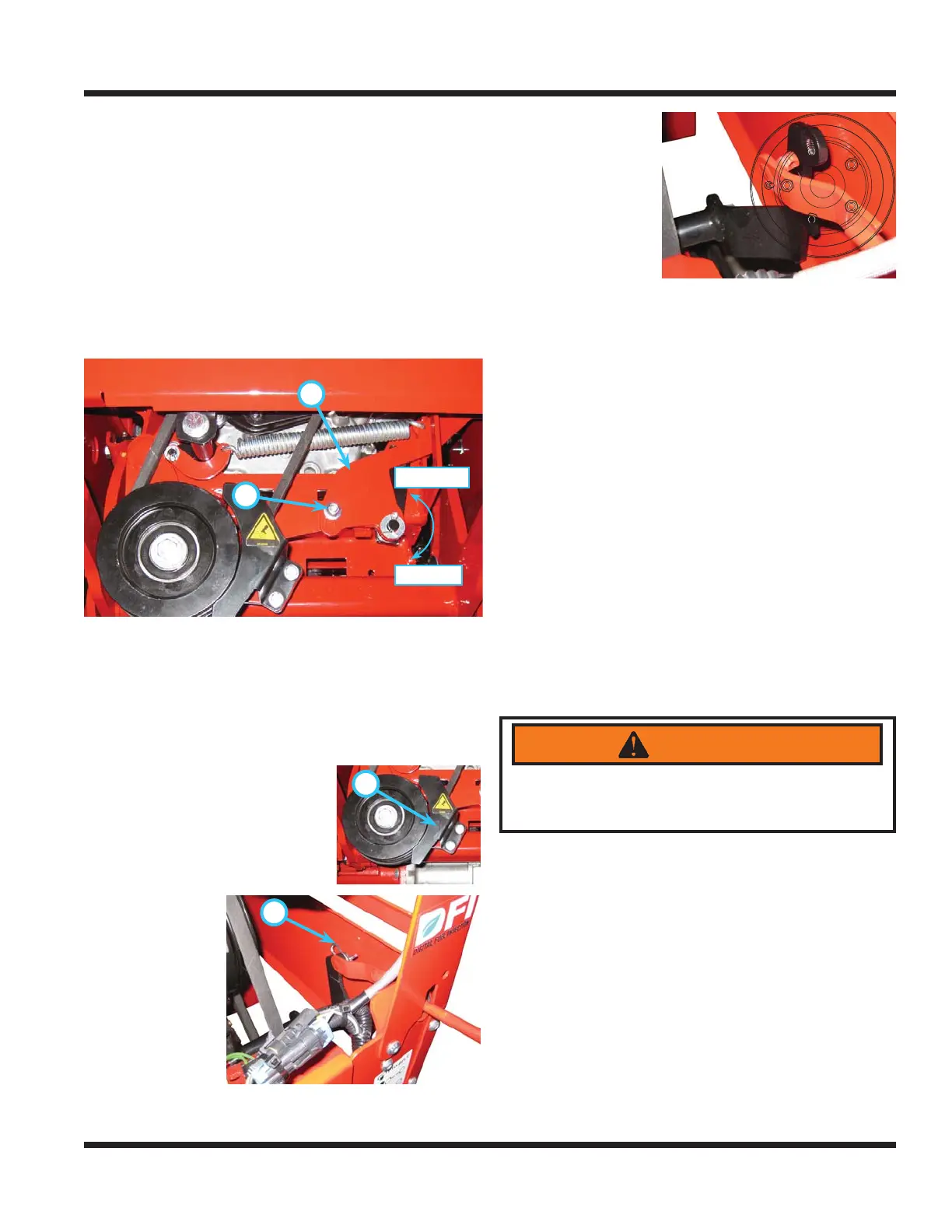
PTO Belt Tension Adjustment
1. Park the power unit on a level surface.
2. Engage the parking brake and shut off the engine.
3. Remove the key from the ignition switch.
4. Pull out on the PTO belt tensioner rod to release
tension on the belt tensioner linkage.
5. Loosen the adjustment bolt (A) and rotate the
tension adjustment link (B) clockwise to increase
the tension applied to the PTO and attachment
belts. Rotate the tension adjustment link coun-
terclockwise to decrease the tension applied to
the PTO and attachment belts.
6.
Decrease
Increase
A
B
Tighten the adjustment bolt securely. Torque to
31 ft-lbs (42 Nm).
PTO Belt Replacement
1. Park the power unit on a level surface.
2. Engage the parking brake and shut off the engine.
3. Remove the key from the ignition switch and
A
allow the engine to cool.
4. Open the engine hood.
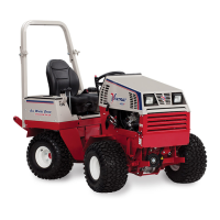
5. Remove the PTO idler pulley
guard (A).
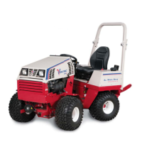
6. Pull the PTO belt tensioner
rod out to release the belt
tension.
B
7. Remove the
hairpin (B) and
washer that
fastens the
belt tensioner
rod to the
belt tension
rocker. NOTE:
on Kubota
models it may
be easier to remove the hairpin from below, prior
to releasing the PTO belt tensioner rod.
8. Remove the belt
tension rod from
the belt tension
rocker.
9. Lift up on the
PTO idler pul-
ley and remove
the belt from the
pulley.
10. Pull the belt up between the PTO tension rocker
and the front grill. If necessary, rotate the PTO
tension rocker to increase the gap between the
rocker and the grill.
11. Push the new belt down between the PTO ten-
sion rocker and the front grill.
12. Install the belt onto the clutch pulley.
13. Lift up on the PTO idler pulley and install the belt
in the rear groove of the idler pulley.
14. Reinstall the PTO belt tensioner rod to the belt ten-
sion rocker and fasten with the hairpin and washer.
15. Reinstall the PTO idler pulley guard. Torque bolts
to 100 in-lbs (11 Nm).
16. Close the engine hood.
Wheel Removal & Installation
Wheel Removal:
1. Park the power unit on a level surface.
2. Engage the parking brake and shut off the engine.
3. Remove the key from the ignition switch.
4. Loosen the wheel lug nuts , but do not remove.
5.
WARNING
If power unit is not adequately supported, the unit
could accidentally fall and trap or crush a person
or appendage, causing severe injury or death.
Lift up the corner of the power unit and secure
with a jack stand.
6. Remove the lug nuts and lift the wheel off the
mounting studs.
Wheel Installation:
1. Place the wheel onto the mounting studs with
the hub side of the rim against the axle hub.
NOTE: if the wheel is equipped with a single
valve stem, the valve stem will be to the outside
of the power unit. If the wheel is equipped with
dual valve stems, there is a decal on the rim that
specifi es the hub side of the rim.
2. Install the lug nuts and tighten by hand until the
wheel is held against the axle hub.
3. Lift the power unit up slightly and remove the
1
2
4
3
5