OPERATIONAL CONTROLS
Operation - 29
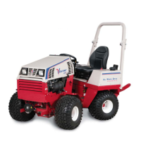
3 Point Hitch & Rear Auxiliary Control
Handles (KK, LL, & MM)
1. 3 Point Hitch Lift
2. 3 Point Hitch Hold
3. 3 Point Hitch Lower
4. 3 Point Hitch Float
5. Left Auxiliary Hyd. Couplers
Direction #1
6. Left Auxiliary Hyd. Couplers
Hold
7. Left Auxiliary Hyd. Couplers
Direction #2
8. Left Auxiliary Hyd. Couplers
Float (if equipped)
9. Right Auxiliary Hyd. Couplers
Direction #1
10. Right Auxiliary Hyd. Couplers
Hold
11. Right Auxiliary Hyd. Couplers
Direction #2
12. Right Auxiliary Hyd. Couplers
Float (if equipped)
10
1
8
6
9
7
5
4
3
2
12
11
The left control handle (KK) controls the position
of the 3 point hitch arms. Pulling up on the handle
raises the 3 point hitch arms. Pushing down on the
handle lowers the 3 point hitch arms. Float position
is attained by pushing the handle down until the
fl oat detent locks the handle in place.
The middle control handle (LL) controls the left
rear set of hydraulic quick couplers. Pull the handle
up to activate the attachment hydraulic cylinder in
direction #1. Push the handle down to activate the
attachment hydraulic cylinder in direction #2.
The right control handle (MM) controls the right
rear set of hydraulic quick couplers. Pull the handle
up to activate the attachment hydraulic cylinder in
direction #1. Push the handle down to activate the
attachment hydraulic cylinder in direction #2.
Rear Auxiliary Quick Couplers (NN)
The rear auxiliary hydraulic quick couplers are used
to control auxiliary functions of attachments that are
being used with the 3 point hitch. The 3 point hitch
includes 2 sets of hydraulic quick couplers.
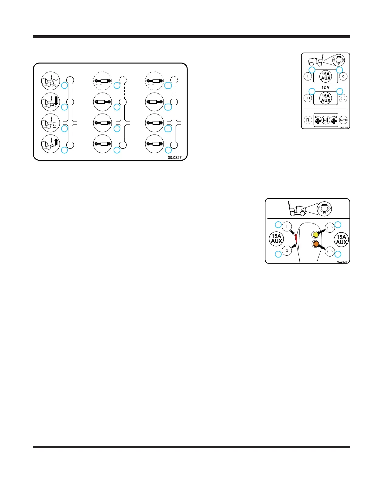
12 Volt Rear Switches & 4-Pin Socket
(OO, PP, & QQ)
The rear 4-pin socket provides
electrical power to rear mounted
attachments that are equipped
with electrical controls.
(e.g. ES220 Spreader)
The switches turn off and on the
electrical power to the rear 4-pin
socket.
Depressing the right portion (1) of
the on/off switch turns on electri-
cal power to the 4-pin socket.
Depressing the left portion (2) of
the switch turns off electrical power.
Depressing the right (3) or left (4) portion of the
mo/off/mo switch turns on electrical power to the 4-pin
socket. Releasing the switch turns off electrical power.
12 Volt Front Switches & 4-Pin Socket
(RR, SS, & TT)
The front 4-pin socket
provides electrical
power to attachments
that are equipped with
electrical controls.
(e.g. broom rotation
actuator, snow blower
discharge chute angle)
The switches turn off and on the elec-
trical power to the front 4-pin socket.
Depressing the top portion (1) of
the on/off switch turns on electrical power to the
4-pin socket. Depressing the bottom portion (2) of the
switch turns off electrical power.
Depressing either the top (3) or bottom (4) momentary
on switch turns on electrical power to the 4-pin socket.
Releasing the switch turns off electrical power.
Electric PTO Remote Socket (UU)
The electric PTO remote socket is used with attach-
ments equipped with a remote PTO switch (e.g.
HG150 generator), allowing the operator to shut off
the power unit PTO from the attachment.
Back Up Alarm (VV)
The back up alarm emits an intermittent signal when
the power unit is operated in reverse to alert nearby
persons that the power unit is backing up.
1. On
2. Off
3. Momentary On
4. Momentary On
1
2
4
3
1
2
3
4
1. On
2. Off
3. Momentary On
4. Momentary On
 Loading...