SERVICE
Service - 57
bolt may affect the neutral switch setting. After
changing the neutral setting, it is possible that
the power unit will not start, due to the neutral
switch being out of adjustment. Refer to the neu-
tral switch adjustment section for procedure on
correctly setting the neutral switch position.
17. Engage the parking brake and shut off the engine.
18. Reinstall the pump cover onto the power unit.
19. Remove the weight from the power unit seat.
20. Remove the power unit from the jack stands or
supporting blocks and return to the ground.
Neutral Switch Adjustment
1.
WARNING
An improperly adjusted neutral switch can result in
erratic engine cranking or unsafe power unit move-
ment. Check the neutral switch position anytime an
adjustment is made to the neutral position.
Park the power unit on a level surface.
2. Engage the parking brake and shut off the engine.
3. Remove the key from the ignition switch.
4. Remove the pump cover from the power unit.
5.
WARNING
The parking brake must be disengaged as part of
the adjustment procedure. Park the power unit on
a level surface and place wheel chocks in front
and back of wheels to prevent the power unit from
rolling forward or backward.
Place wheel chocks in front and back of wheels
to prevent power unit from rolling.
6. Disengage the parking brake.
7. Turn the ignition key to the key switch’s Run
position to activate the electrical system, but do
not start the engine.
A
8. Open the power
unit’s hood and
locate the trac-
tor control module
(TCM) The neutral
switch input light
(A - 2nd light down
from the top on the
left side of the TCM)
will be used as an
indicator for when the
neutral switch is on
or off.
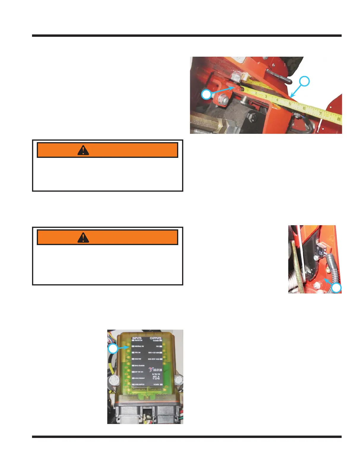
9. Measure the distance between the front frame (B)
and the pump arm (C) and record for reference.
B
C
10. Move the SDLA lever slowly in the forward
direction while watching the neutral switch input
light. When the light goes out, stop the SDLA
lever and measure the distance between the
front frame and the pump arm. This measure-
ment should be a minimum of 1/32” (.8 mm) less
and a maximum of 1/16” (1.6 mm) less than the
measurement taken in step 9 (ex. if measure-
ment in step 9 was 4” (101.6 mm), the measure-
ment when the light goes out must be between
3-31/32” (100.8 mm) and 3-15/16” (100 mm)).
NOTE: it may be helpful to have an assistant to
take the measurements.
D
11. If the measurement is not
within the specifi ed range,
adjust the neutral switch
mount (D) by loosening the
two mounting bolts and slid-
ing the mount in the neces-
sary direction. Tighten the
switch mount hardware to
100 in-lbs (11 Nm).
12. Repeat steps 10 and 11 as needed until the
measurement is within the specifi ed range.
13. Turn off the key switch and close the engine hood.
14. Engage the parking brake.
15. Reinstall the pump cover onto the power unit.
16. Remove the wheel chocks.
17. If you are unsure of the correct procedure to
adjust the neutral switch, or if you are unable
to attain the correct setting, contact your autho-
rized Ventrac dealer for assistance.
 Loading...