Operation - 17
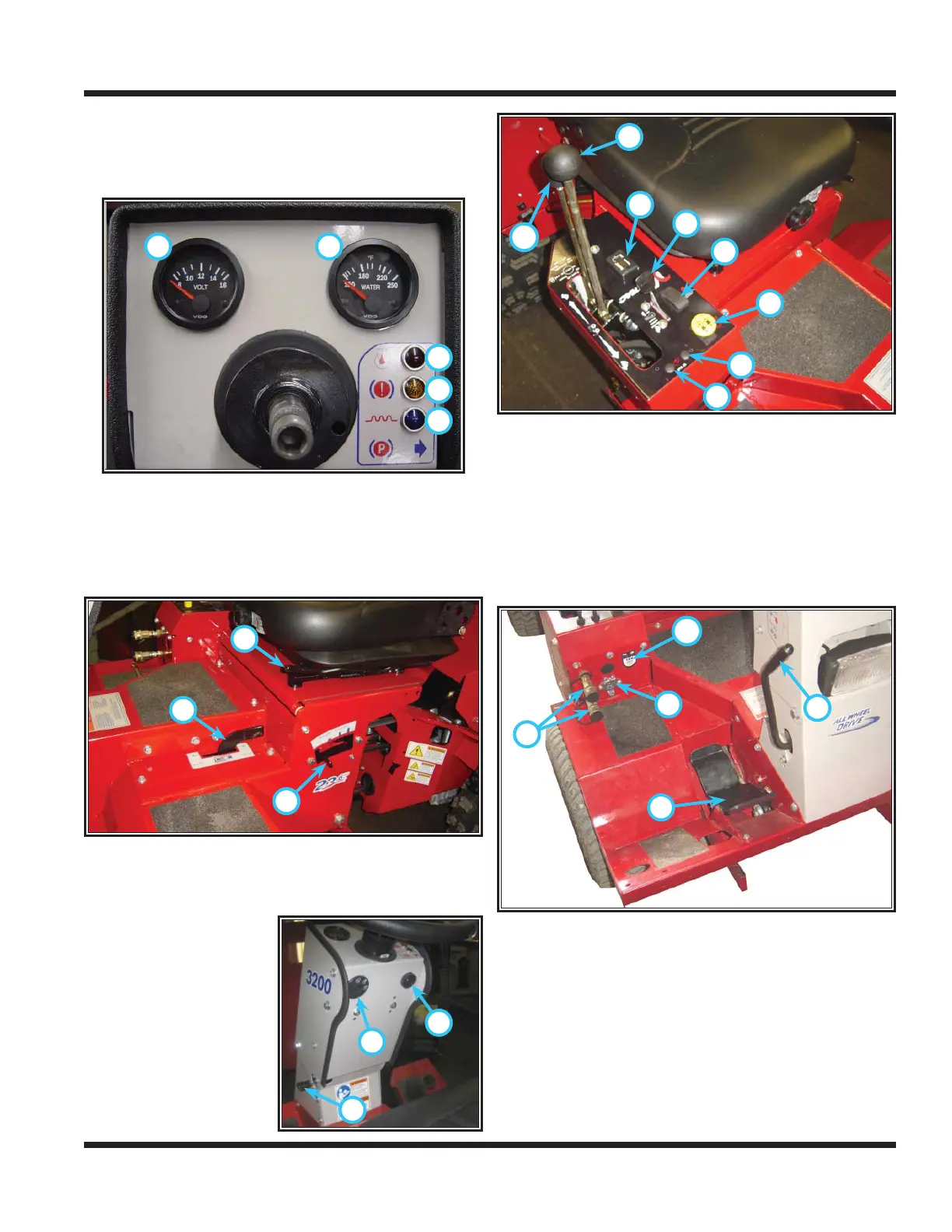
Operational Control Locations
The following images are referenced with letters to
help identify the locations of operational controls for
this power unit.
A
B
C
D
E
A - Volt Gauge
B - Engine Coolant Temperature Gauge
C - Engine Oil Pressure Warning Light
D - Water In Fuel Warning Light
E - Glow Plug Indicator Light
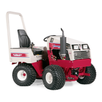
F
G
H
F - Attachment Lock Lever
G - Weight Transfer Adjustment Lever
H - Seat Slide Adjustment Lever
I
J
K
I - Steering Tilt Adjust-
ment Lever
J - Ignition Key Switch
K - High Temperature
Sensor Alarm
L
M
N
O
P
Q
R
S
L - Primary S.D.L.A. Control Lever
M - Secondary S.D.L.A. Control Lever
N - Tachometer/Hour Meter
O - Throttle
P - Light Switch
Q - PTO Switch
R - 12 Volt Switch (Momentary On/Off/On)*
S - 12 Volt Switch (On/Off)*
T
U
V
W
X
T - Selector Lever/Parking Brake
U - Foot Pedal
V - Auxiliary Hydraulic Quick Couplers
W - 12 Volt Outlet*
X - 12 Volt 4-Pin Socket*
OPERATIONAL CONTROLS
*Optional equipment