16 VX-1700 Series (EXP Version) Service Manual
PA-4 Unit Alignment
PRE-DRIVER SECTION IDLING CURRENT ALIGNMENT
Connect the 50 Ohm Dummy Load to the ANT
jack.
Remove the shorting-plug from J5005 on the PA-
4 Unit, then connect the DC Ammeter to J5005
(pin 1: “–” lead, pin 2: “+” lead).
Set VR5001 on the PA-4 Unit fully counter-clock-
wise.
Tune the radio to 7.500 MHz, USB mode.
Key the transmitter (connect pin 3 of the MIC jack
to GND) with no microphone input, and adjust
VR5001 for 150 mA (±10 mA) on the DC Amme-
ter.
Disconnect the DC Ammeter, and replace the
shorting-plug into J5005.
DRIVER SECTION IDLING CURRENT ALIGNMENT
Connect the 50 Ohm Dummy Load to the ANT
jack.
Remove the shorting-plug from J5007 on the PA-
4 Unit, then connect the DC Ammeter to J50074
(pin 1: “–” lead, pin 2: “+” lead).
Set VR5002 and VR5003 on the PA-4 Unit fully
counter-clockwise.
Tune the radio to 7.500 MHz, USB mode.
Key the transmitter (connect pin 3 of the MIC jack
to GND) with no microphone input, and adjust
VR5002 for 500 mA (±50 mA) on the DC Amme-
ter, then adjust VR5003 for 1 A (±50 mA) on the
DC Ammeter.
Disconnect the DC Ammeter, and replace the
shorting-plug into J5007.
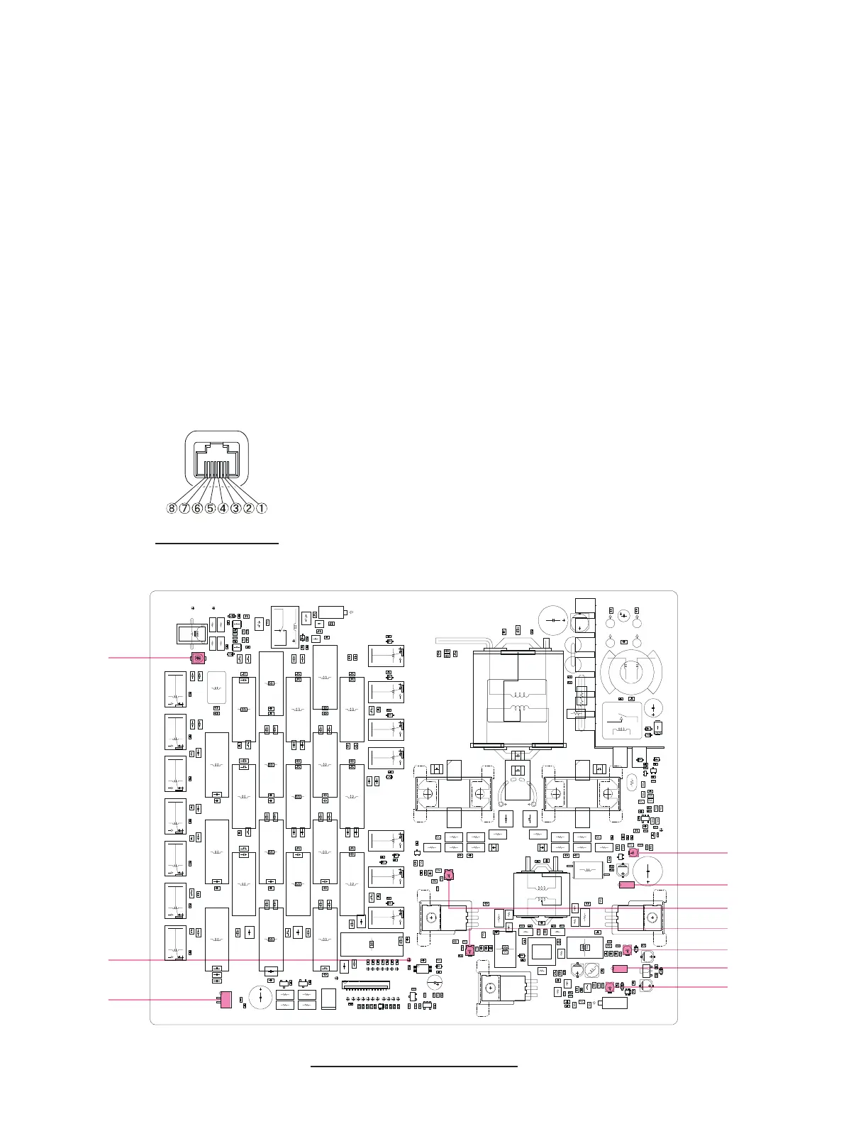
PA-4 UNIT ALIGNMENT POINTS
J5007
VR5004
VR5001
J5005
TC5001
TP5028
MIC JACK PINOUT
VR5002
VR5003
VR5005
J5001
 Loading...