VX-2100/-2200 SERIES OPERATING MANUAL 3
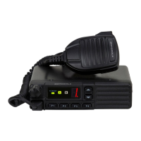
CONTROLS & CONNECTORS
(
VX-2100
)
Channel Number Indicator
Indicates the operating channel.
Blinks the squelch setting level (0-9, A, b, and C) while adjusting the squelch
threshold level. Appear the decimal point “.” when selecting the Scan enabel
channel.
Transceiver Status Indicator
The “A” and “B” indicators show current transceiver status, which can be cus-
tomized via programming by your VERTEX STANDARD dealer to meet your
communications/network requirements. The possible “A” and “B” displays are
explained below.
TX/BUSY Indicator
Indicates transceiver’s Transmit/Receive Status
Steady Red: Transmitting in progress
Steady Green: Signaling Off
Blinking Green: Busy Channel/Squelch Off
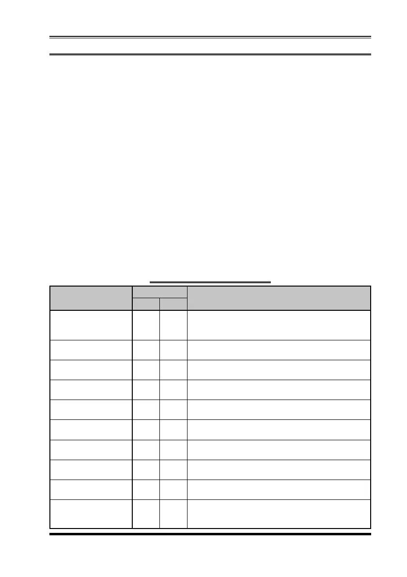
TRANSCEIVER STATUS INDICATOR
MONI
LOW
TA
(
Talk Around
)
Encryption
(
Requires optional Unit
)
Emergency
Horn Alert
Public Address
Key Lock
EXT ACC
RFC
INDICATOR
A B
This indicator is Illuminated constantly when CTCSS-
or DCS-controlled squelch is disabled. The indica-
tor blinks while the audio is passing normally.
Illuminates the indicator when the radio’s transmit-
ter is set to the “Low Power” mode.
Illuminates the indicator when the “Talk Around” func-
tion is activated.
Illuminates the indicator when the “Voice Scrambler”
function is enabled.
Illuminates the indicator when the “Emergency” fea-
ture is activated.
Illuminates the indicator when the “Horn Alert” fea-
ture is activated.
Illuminates the indicator when the radio is turned to
a PA amplifier.
Illuminates the indicator when the front panel’s keys
are locked.
Illuminates the indicator when the output port on the
Accessory Connector is turned to “ON.”
Illuminates the indicator when the radio is the “Ready
for Communication” condition while operating with
the 2-Tone or 5-Tone signaling.
STATUS DESCRIPTION
 Loading...