VXR-9000 UHF Service Manual
Alignment
G-7
PLL Reference Frequency
Important Note: (1) Do not this adjustment unless you have a
high-performance frequency counter. (2) This adjustment
needs to add a “Chip Resistor” on to the Main Unit. For fur-
ther details contact to Vertex Standard.
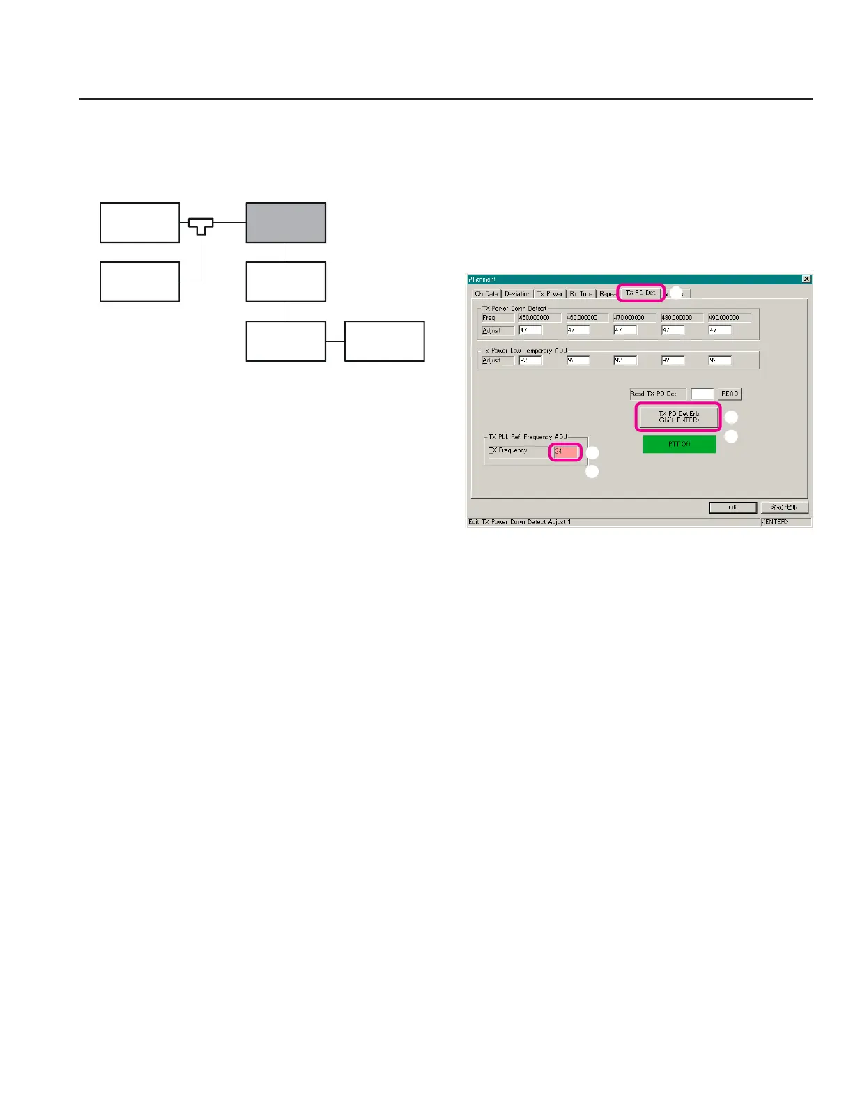
Setup the test equipment as shown below.
Open the “Alignment” window, then click the left
mouse button on the “TX PD Det.” tab to move to the
“TX PD Det.” screen.
Click the left mouse button on the “TX Frequency” box
(highlighted in “pink”).
Click the left mouse button on the “TX PD Det. Enb”
button to actitvate the transmitter (the “TX PD Det.
Enb” label is changed to “PTT Off”).
Press the
[
Page Up
]
/
[
Page Down
]
key so that the Fre-
quency Counter reading is “Low Band Edge Fre-
quency” ±100 Hz.
Click the left mouse button on the “PTT Off” button
to disable the transmitter (the “PTT Off” label is re-
turned to “TX PD Det. Enb”).
50-ohm
Dummy Load
Computer
(
CE60
)
Frequency
Counter
VXR-9000
FRB-6
MIC
TX ANT
Samplin
Coupler
FIF-10A
or
FIF-12
 Loading...