VXR-9000 UHF Service Manual
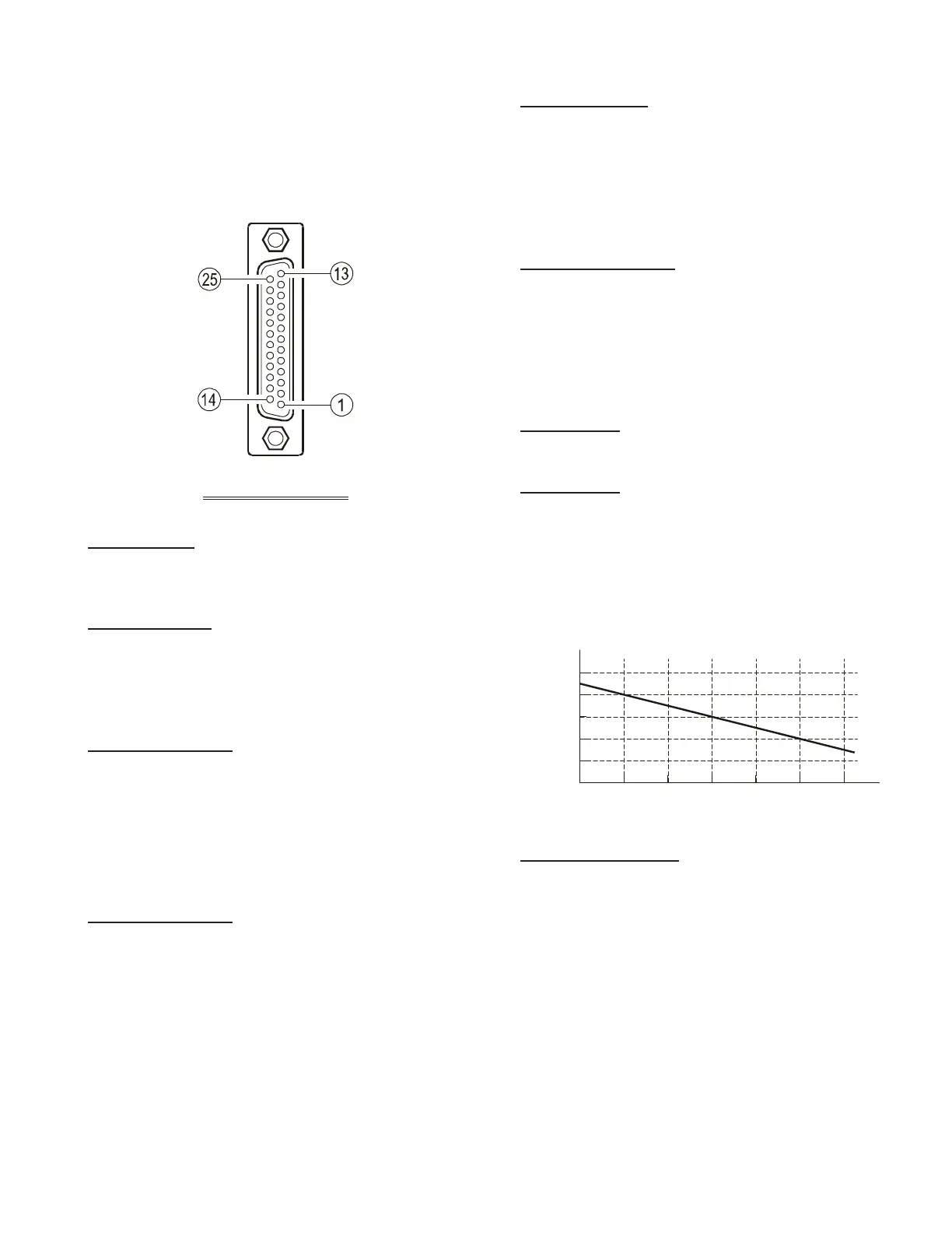
DSUB 25-pin Accessory Connector
The VXR-9000 repeater is provided with a 25-pin DB-25F
female connector for interconnections to accessories.Use
a DB-25M 25-pin male connector to connect accessories
to the repeater. The pins on the accessory connector are
explained in detail as follows:
Pin 1: GND
Chassis ground for all logic levels and power supply re-
turn.
Pin 2: +13.6 V
[
POWER SUPPLY
]
This pin provides 13.6 Volts, 2.0 A, DC from the repeater
supply. There is a internal 3 A fuse to prevent damage to
the repeater.
Pin 3: TX AF IN
[
ANALOG TRANSMITTER INPUT
]
(
VOICE BAND: 300 ~ 3,000 HZ
)
This pin is s audio input. Input impedance is 600 Ohms.
This audio is injected before the splatter filter stage, so
excess signal input levels are clipped.
Use shielded cable to connect to this pin, and connect the
shield to GND.
Pin 4: TONE IN
[
TRANSMITTER INPUT
]
(
SUB-AUDIBLE BAND: 5 ~ 250 HZ
)
This pin is sub-audible tone produces 10% of full system
deviation. The nominal input voltage is 77.5 mVrms. The
input impedance is@600 Ohms, and has a flat response
characteristic (repeater deviation is constant for a given
signal level over the frequency range of 5 ~ 250 Hz). In-
jecting too high a voltage here causes over-deviation of
CTCSS or DCS, degrading performance. Use shielded
cable to connect to this pin, connecting the shield to GND.
B-1
DB-25 PIN NUMBERING
Pin 5: TX ATT
This output is intended for controlling an external coaxial
switching relay. It is an open drain output which can sink
approx. 1.5 A when active. The delay time which is be-
tween the repeater cause to transmit mode and this port
switches to ground can be programmed by your VERTEX
STANDARD dealer.
Pin 6: DISC OUT
[
A
NALOG OUTPUT
]
(
W
IDE-BAND: 0 ~ 3,000 HZ
)
Received signals with full system deviation produce 350
mVrms audio at this pin. The output impedance is 600
Ohm, and is extracted before the de-emphasis and squelch
circuitry. Use shielded cable to connect to this pin, and
connect the shield to GND.
Pin 7: N.C.
No connection.
Pin 8: RSSI
[
ANALOG OUTPUT]
A DC voltage proportional to the strength of the signal
currently being received (Receiver Signal Strength Indi-
cator) is provided on this pin. This low impedance output
is generated by the receiver IF sub-system and buffered
by an internal op-amp. Typical voltages are graphed as
follows:
Pin 9: COAX. SW
[
LOGIC OUTPUT
(
ACTIVE LOW
)]
This output is intended for controlling an external coaxial
switching relay. It is an open drain output which can sink
approx. 1.5 A when active. This signal only switches if the
repeater has been programmed for “SIMPLEX” mode. If
programmed for “DUPLEX,” the signal remains open
(high impedance) at all time.
0
–60 –100 –110 –120 (dBm)–70 –80 –90
0.5
1.0
1.5
2.0
2.5
DC V
Input Signal Level
R
S
S
I
O
u
t
p
u
t
V
o
l
t
a
g
e
 Loading...