MFU
8
13
W2453X1
W2453X1
J6
21
J3
1+
1-
2+
2-
LCU+ controller busbar socket
J8
1
8
W80
J7
1 2
1
2
3
4
5
6
7
8
9
10
11
12
13
14
15
16
17
18
19
20
21
22
23
24
25
26
27
28
29
30
31
32
33
34
35
36
37
38
39
40
41
42
43
44
45
46
47
48
49
50
13-J8-1
31-J42-CAN-
M221S
7
18-J1-1
11-2
11-1
31-J42-CAN+
13-J7-1
13-J7-2
13-J8-2
13-J8-3
13-J8-5
13-J8-4
13-J8-6
13-J8-7
13-J8-8
8-QFB2-1
8-QFB1-1
10-2
10-1
W80
W80
W84
W84
W80
W80
W80
W80
W80
W80
W80
9-BUS+-2
X6-1
X5-1
8-PL-1
W80
9-BUS+-1
W80
W80
8-PL-1
18
M34C3C1
18-J1-2
W80
J4
3+
3-
4+
4-
DO3
DO4
DO1
DO2
1
2
3
5-2
W07
2
1
1
2
PL
1
2
1
2
7-30
QFB1
QFB2
7-28
7-20
7-22
18-J2-1
18-J2-2
W80
1
2
7-45
7-43
NPL
8-B-
1
2
1
2
QFD1
QFD2
1
2
QFD3
1
2
QFD8
NPL
1
2
1
2
QFD9
QFD12
PL
0V
PE
5
1
BUS+
9
RB
10
KM1
11
KM2
12
2
9-2
1
7-29
W84
W80
W80
W84
W80
W80
7-35/7-49/7-50
9-BUS+-2
12-1
W84
4
2
W80
9-BUS+-1
X5-1
W80
8-QFD
Front view
1
2
15-J7
W80
W06
7-31/7-46
18-J2-3
W84
W80
Front top view (open the panel)
2
J2
1
2
3
J1
1
7-39
7-41
12-1
12-2
8-PL-1
W84
W84
8-PL
QFA
1
SPD1
2
QFA2
3
L1
1
3
2
4
N
L
N-1
PE
1
2
N L
2-L
3
4
W01W01
COM
NC
NO
W80
7-42
7-40
W01
W01
2-N-2
31-J1-L/31-J2-L/31-J3-L/31-J4-L/3-2
2-N-2
W01
W01
N-2
31-J1-N/31-J2-N/32-J3-N/32-J4-N
3-4/1-4
8-PL-2
W06
J6
J3
15
M2433X2
J7
J5
J1 J2 J4
v-
v+
PE
5-4
W06
DCSPD
15-J6
W06
31-H5
W07
2-NC
2-COM
H5
DC-
DC-
L N
L
N L N
L N
J2
J1
J4
J3
H2
H1
J13
J11
H3 H4
DC+
U1 U2
DC+DC-
J12 U3
DC+
U4
DC+
DC-
J14
U11
U12
U13
U14
DC-
DC+
1-2
2-N-1
1-2
J41
CAN+CAN-
J42
CAN+ C AN-
W01
1-2
1-2
W80
31
W2493ZX1
W80
7-4
7-2
W01
W01
W01
2-N-1
2-N-1
2-N-1
5-4
W07
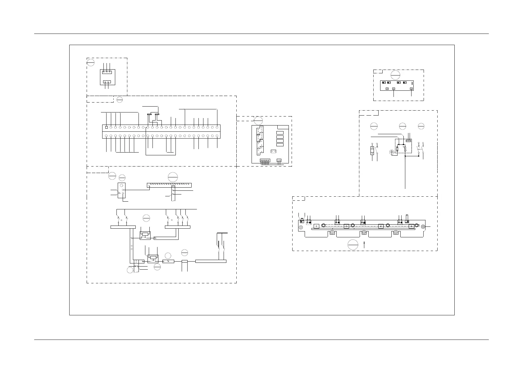
Front view
MFU DC wiring diagram
Rear top view
To SPD PE bar
To the positive busbar of the module
To the negative busbar of the module
Note: Connet X5-1 to the X6-1 and the cable of the temperature sensor.
User interface board 1
Single-phase AC
input with the SPD
Subrack
Front top view of the back plat (with the controller and rectifier)