Appendix 3 Wiring Diagram 33
NetSure 731 A41 Subrack Power System User Manual
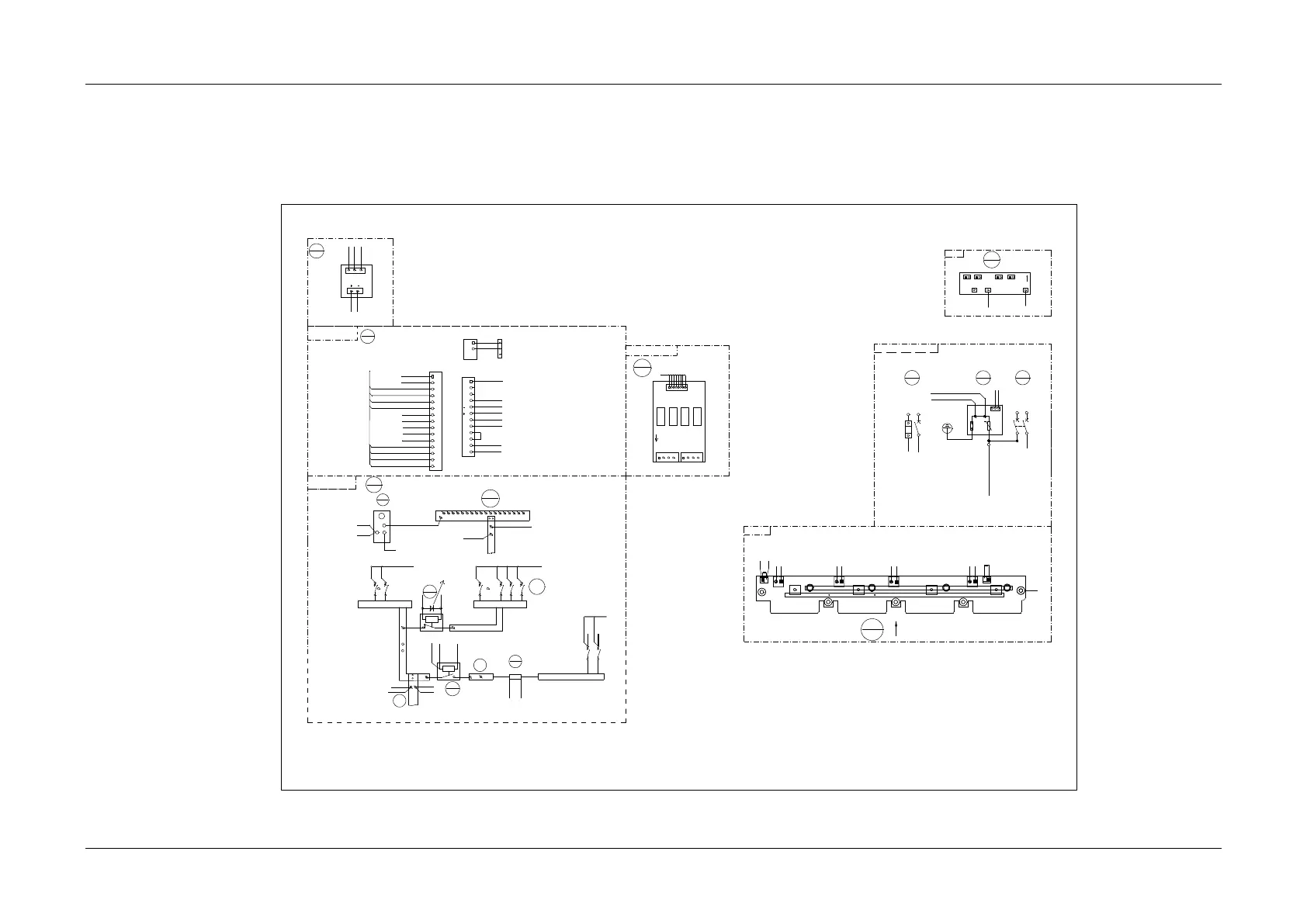
Appendix 3 Wiring Diagram
MFU DC wiring diagram
MFU
8
Rear top view
13
M225S1X1
User interface board 1
monitor motherboard
M225S
7
18
M34C3C1
Subrack
1
3
2
5-2
W07
2 1
1
2
PL
1
2
1
2
7-J6-9
QFB1
QFB2
7-J6-10
7-J6-8
7-J6-7
18-J2-1
18-J2-2
W80
1
2
7-J7-11
8-PL-2
NPL
8-B-
1
2
1
2
QFD1
QFD2
1
2
QFD3
1
2
QFD8
NPL
1
2
1
2
QFD9
QFD12
PL
0V
To the positive busbar of the module
PE
5
1
BUS+
9
RB
10
KM1
11
KM2
12
2
9-2
1
W80
7-J6-11
7-J6-11
W84
W80
W80
W84
W80
7-J7-4/7-J7-12
9-BUS+-2
12--KM2-1
W84
4
2
W80
Single AC input (with AC SPD)
Front view
1
2
11-KM1-2
W80
W80
7-J7-1
W80
Right view
H5
DC-
DC-
L N
L N L N
L N
J2
J1
J4J3
H2
H1
J13
J11
H3 H4
DC+
U1 U2DC+DC-J12 U3
DC+
U4
DC+
DC-
J14
U11 U12
U13
U14
DC-
DC+
1-2
2-N-1
1-2
J41
CAN+CAN-
J42
CAN+ CAN -
W01
Front top view of the back plat (with the controller and rectifier)
1-2
1-2
W80
8-PL
QFA
1
SPD1
2
L
1 3
2 4
N
L
N-1
PE
COM
NC
NO
W80
7-J7-7
7-J7-8
W01
W01
31-J1-L/31-J2-L/31-J3-L/31-J4-L/3-2
2-N-2
W01
W01
N-2
31-J1-N/31-J2-N/32-J3-N/3 2-J4-N
1-4/3-4
31
W2493ZX1
2
J2
1
2
3
J1
1
7-J7-5
7-J7-6
12-KM2-1
12-KM2-2
8-PL-1
W84
J6
1
2
3
4
5
6
7
8
9
10
11
12
13
14
15
J7
1
2
3
4
5
6
7
8
9
10
11
12
J2
1
2
3
X4-1
CAN-
CAN+
13-J1-1
10-RB-1
10-RB-2
8-QFB1-1
8-QFD
13-J1-5
8-PL-1
9-BUS+-1
18-J1-1
2-COM
2-NC
11-KM1-1
9-BUS+-1
J1
1
8
DO3
DO4
DO5
DO6
J3
J2
W80
W80
13-J1-2
13-J1-3
13-J1-4
13-J1-6
13-J1-7
13-J1-8
W80
8-QFB2-1
W80
18-J2-3
18-J1-2
W84
W80
W80
W80
W80
W80
W80
To subrack PE bar
To SPD PE bar
This diode cintains in the W80 cable
1
2
N L
2-L
3
4
W01W01
2-N-2
QFA2
3
W80
7-J6-2
7-J6-1
31-J42-CAN-
31-J42-CAN+
8-PL-2
J6
J3
15
M2433X2
J7J5
J1 J2 J4
v-
v+
PE
5-4
W06
DCSPD
15-J6
W06
15-J7
W06
8-QFD
W80
door
W80
W80
W80
W01
W01
W0 1
2-N-1
2-N-1
2-N-1
31-H5
W07
5-4
W07
W06
socket
Top view
Note: Connet X4-1 and the cable of the temperature sensor.
To the negative busbar of the module
Pull out the controller