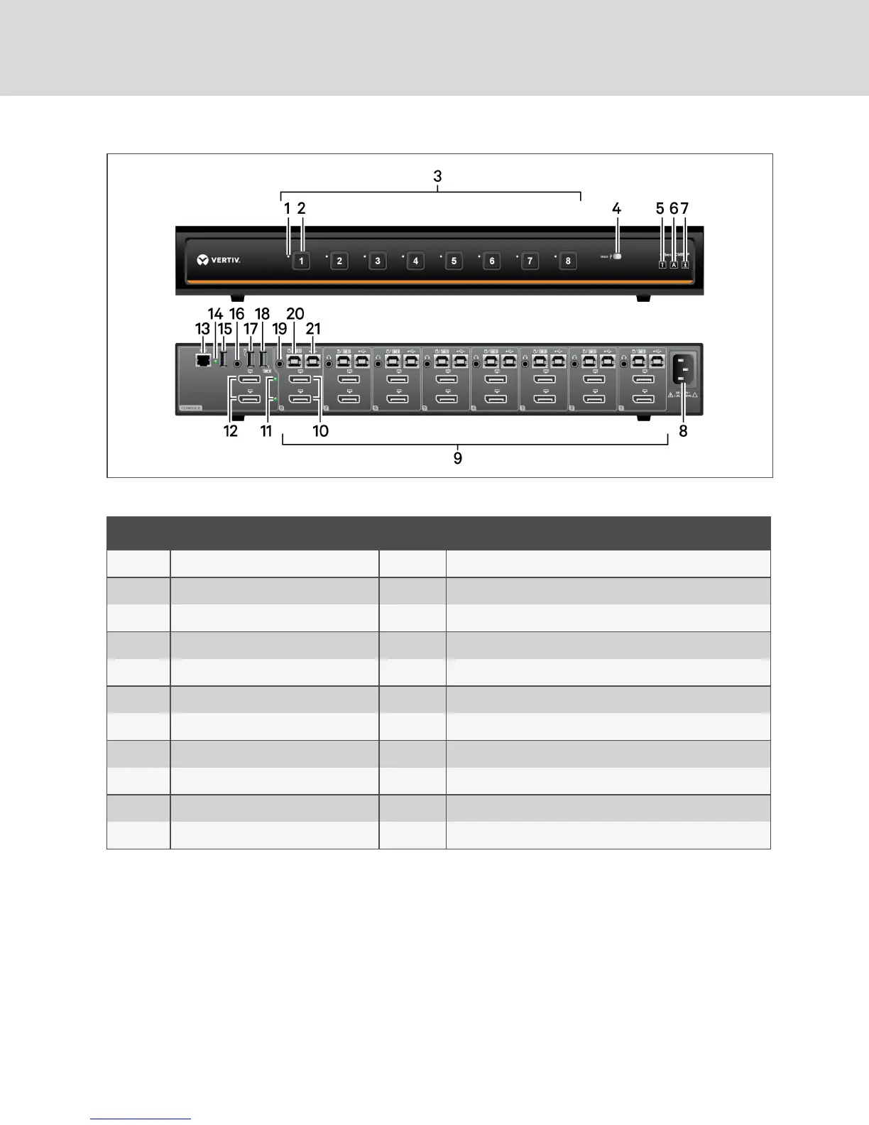
Figure 2.11 SC 985DPKVMSwitch
ITEM DESCRIPTION ITEM DESCRIPTION
1 LED DPP channel indicator 12 CONSOLE DisplayPort video ports
2 LED channel selector 13 CONSOLERemote Control Unit (RCU) port
3 PCport selectors 14 CONSOLE DPP LED connection indicator
4 DPP freeze button 15 CONSOLE DPP USB Type-A port
5 Num lock indicator 16 CONSOLE audio jack (3.5 mm stereo)
6 Caps lock indicator 17 CONSOLE mouse USB Type-A port
7 Scroll lock indicator 18 CONSOLE keyboard USB Type-A port
8 AC power inlet 19 PC audio jack (3.5 mm stereo)
9 PC ports 20 PC keyboard/mouse USB Type-B port
10 PC DisplayPort video ports 21 PC DPP USB Type-B port
11 Status LEDs
Table 2.11 SC 985DP KVM Switch Description
2.1.1 Switching between computers
After turning on the switch, the default channel is channel one. You can select which computer to operate
using the front panel push-buttons. The LED number illuminates to indicate which computer is currently
selected. Allow approximately one second for the video signal to sync after switching computers.
After selecting a new channel, the mouse cursor is positioned in the center of the selected computer
display. When you select a new channel, the mapping for the keyboard, mouse, audio and USB device also
changes to the specified channel.
Vertiv™ | Cybex™ SC Switching System Installer/User Guide
14

 Loading...


