Micro-Controller
Vertiv | Liebert CRD10 | User Manual 73
Table 6-2 Functional Description
Press this button to enter the main page to see the systems primary data readings.
Press this button to display the main menu page by page and enter the various sub-menus
Press this button to enter the temperature and humidity settings page, t which can set the
system temperature and humidity and the control mode.
Click this button to enter the curve interface, you can view the average return air temperature,
the remote average temperature, the average air supply temperature, and the average air
supply humidity of 0~48Hour.
Displays the current time
Displays the unit address
Displays the display address
Unit is turned off, press the button at least 2s, the unit will boot; the unit is running, Press on
the button at least 2s, the unit will shut down;
Press the unlock button, enter the correct user login password to log in; the menu icon appears
after logon to set parameters; Click the unlock button to enter the unlocked interface.
Display the current operating status of the unit (shutdown, operation, standby, lock,
communication interruption).
Press the toggle button to switch between the graphical display mode and the list display mode
Press this button to switch between the current sensor readings and alarm pages
Display the current setting value of the unit and the environmental conditions of the
equipment, as described in the following main interface control mode
Displays the current state of the unit
Displays the current operating status of each sensor and its respective components
Displays all the current alarms and its occurrence time
6.3.2
Main Interface Control Mode
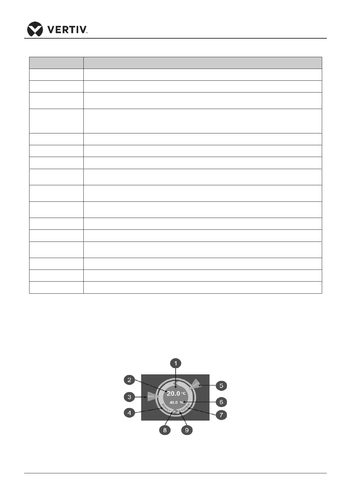
The main interface is divided into temperature control mode, humidity control mode, temperature value in
current control mode, theoretical supply air humidity value, three read-only status of temperature /
humidity setting value.
Figure 6-3 Control Mode Diagram