Micro-Controller
Vertiv | Liebert CRD10 | User Manual 74
Table 6-3 Description of control mode diagram
The colors in the circle are green, gray, and red. For details, see Table 6-4.
The measured supply air temperature value changes with the change of the compressor’s current control mode.
The humidity setting value changes and rotates clockwise between 30-150 polar coordinate angles according to
the range of humidity setting value. When the humidity setting is the minimum value, the value is 30 degrees in
the polar coordinate, when the humidity setting value is the maximum value, and the humidity setting value is
150 degrees in the polar coordinate.
Humidity control is the air supply humidity control by default, showing “supply”
The temperature setting value changes and rotates clockwise between 30-150 polar coordinate angles according
to the range of temperature setting value. When the temperature setting is the minimum value, the value is 30
degrees in the polar coordinate, when the temperature setting value is the maximum value, and the temperature
setting value is 150 degrees in the polar coordinate.
Theoretical air supply humidity value
The current control mode of compressor is air supply humidity control by default, showing “supply”
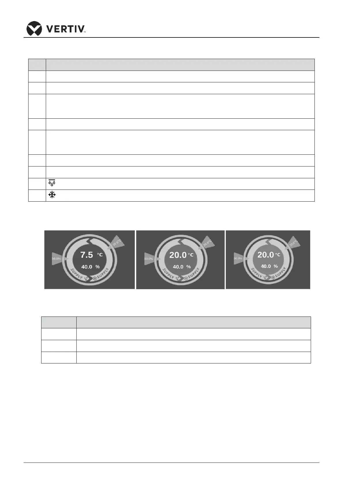
There are three types of main interface unit status colors, as shown in Figure 6-4.
Figure 6-4 Unit Status Color
Table 6-4 Unit Status Color Description
System Status Description
Power-on sensor data is not in the normal range or is invalid
Power on status is within the normal range