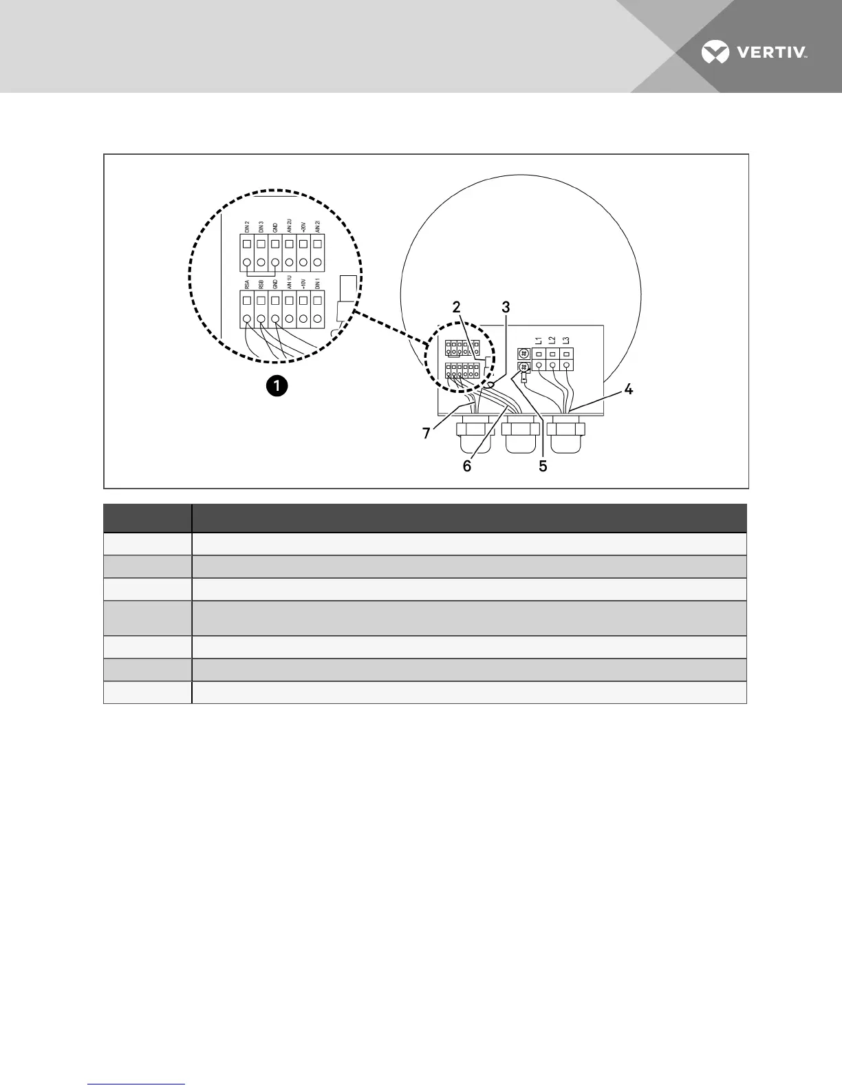
Figure 8.5 Internal wiring of EBM fan in Condenser
Item Description
1 Wiring terminal detail.
2 Not used on last fan.
3 Must be cable-tied together away from high-voltage terminals
4
Edge of out cable jacket should only extend far enough into enclosure to be able to make the electrical
connections.
5 GND
6 Communication cable connected to the next fan (not used on the last fan).
7 Communication cable from the previous fan or from the electric box.
4. Remove hardware that attaches the EC fan to the condenser.
5. Use lifting equipment or an adequate number of personnel to remove the EC fan from the
condenser.
NOTE: A spreader bar may be required for the lifting equipment if only one technician is performing the
fan replacement.
6. Install a spreader bar over the new EC fan if only one technician is performing the fan
replacement.
7. Verify that the wire harness on the new EC fan is secured out of the way before lifting the fan.
8. Verify that the lifting cable/chains are not in contact with fan blades before lifting the new fan
into place on the condenser.
9. Install the new fan in the condenser and connect the mounting hardware.
10. Verify that the fan blades rotate freely when installed in unit.
11. Install the new cable glands included with the new EC Fan. Torque for the cable glands is:
• 630-mm and 710-mm fans: 19.5to24.75 in-lb (2.2 to 2.8 Nm)
• 800-mm fans: 32.75 to 38 in-lb (3.7 to 4.3Nm)
Dispose of the old cable glands once the new glands are installed.
8 Maintenance 37