12. Add a compression nut to the wire—Do not tighten the nut.
13. Reconnect the wiring to the proper terminals and verify that the run jumper is in place. See
Figure 8.4 on page36, and Figure 8.5 on the previous page, for wiring details.
• The torque for the electrical terminals is 11.5 in-lb (1.3 Nm). Tighten the compression nut
to a torque of 22 in-lb (2.5 Nm).
14. With the PCB powered, the board display should read F00.
15. Press the ESC button.
16. Press the UP-arrow button once:
• If P- - is displayed, perform step 17.
• if P- - is not displayed, perform steps 18 through 46.
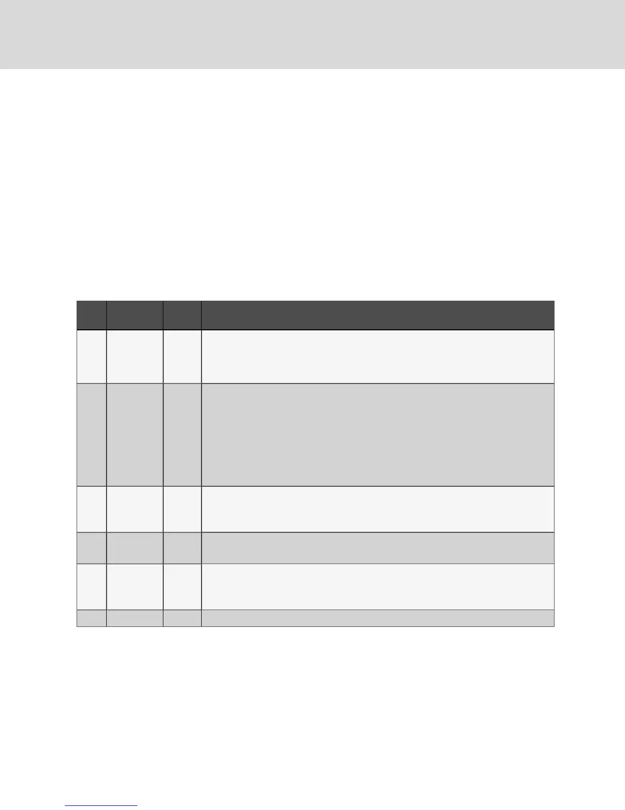
17. If P- - is displayed, press the ENT button to enter the P- - Menu.
The P- - Menu allows compact set-up/preparation of the condenser in the factory or in the
field. Use the functions described in Table 8.1 below, to establish a default control
configuration for the board.
Item
ID
Meaning Default Notes
P01
Enter
Preparation
Mode
0
Setting this value to ‘1’ enables preparation mode. All other ‘P—‘menu items are disabled until this
value is ‘1’. Note that control operations may be affected during preparation mode, therefore the
cooling unit should be off. Setting this value back to ‘0’ creates new default values based upon
selections in this menu. After default values are established, the board exits preparation mode and
reboots.
P02
Automatic
VSD
Configuration
1
This item should only be used to address the VSDs for the unit. The value entered indicates the
model of the VSD:
1 – EBM
2 – Ziehl-Abegg
3 – Fans Tech
All fans must be the same model to use this parameter. When ENT is pressed, the board will
operate and power contactors for the VSDs and assign ModBus addresses. This procedure may
take up to 5minutes to complete.
P03
Refrigerant
Type
2
1 = R22
2 = R407C
3 = R410A
P04
Number
of Circuits
1
1 = Single Circuit
2 = Dual Circuit
P05
Liebert®
Lee Temp
Option
0
0 = No Lee Temp installed
1 = Liebert® Lee-Temp installed
P06 Condenser 1 0 = Small
Table 8.1 P-- menu items and definitions
18. Turn the power On.
19. The control board flashes F00 on the display when it has completed its boot cycle.
20. Press the ESC button.
21. Use the UP or DOWN arrow button until C-- displays.
22. Press the ENT button.
23. Use the UP or DOWN arrow button until C03 displays
24. Press the ENT button.
Vertiv | Liebert® DSE500™ Installer/User Guide
38