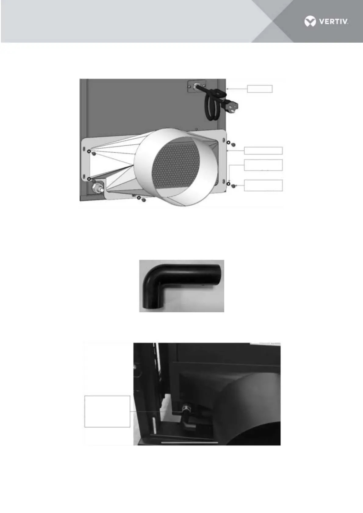
3.4.3 Installing the transition part on VRC1 unit
The transition part is installed on the condensing air discharge side. On this step, it can be installed with 6
M5x12 pan-head screws and 6 M5 contact washers. Torque=4.0 Nm (2.95 lb-ft)
Figure3-12 Transition part installation
3.4.4 Connect the L-shape pipe to the drain fitting
The L-shape pipe, ID=16 mm (5/8’’) is placed in the pump kit.
Figure 3-13 L-shape pipe
Connect the L-shape pipe to the drain fitting. Use a cable tie to fasten it.
Figure 3-14 Connect the pipe 4 to the drain fitting