EasyManua.ls Logo

Vertiv VRC100 - Page 35

Vertiv VRC100
70 pages
Print Icon
To Next Page IconTo Next Page
To Previous Page IconTo Previous Page
Loading...
23
Vertiv I VRC Self-Contained System I User Manual
3.4.5 Installing the pump
1. The pump bracket is comprised of two parts, pump bracket 1 and pump bracket 2.
Figure 3-15 Pump bracket
2. Loose the screw and remove the pump bracket part 2 from the pump bracket part 1. The pump is
pre-installed on the pump bracket part 1 in factory.
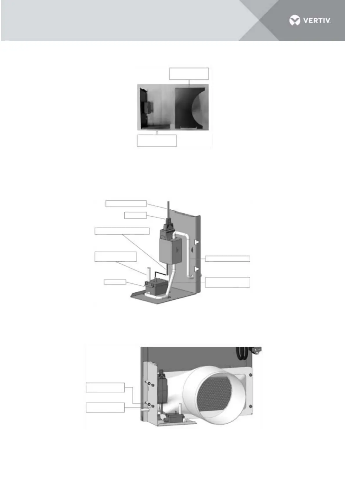
Figure 3-16 Pump is pre-installed on the bracket 1
3. Install the pump bracket part 1 on the condensing air discharge side of the VRC1, tightened by two
pan-head screws with contact washer (M5 x 12). Torque=4.0 Nm (2.95 lb-ft).
Figure 3-17 Install the pump bracket part 1 on the unit
Condensate pump
bracket part 2
Condensate pump
bracket part 1
Pump power cable
Pump
Pump communication cable
Pipe 1 ID=6mm (1/4")
L=60mm (2.4")
Pipe 3 ID=6mm (1/4")
Pipe 2 ID=6mm (1/4")
L=300mm (11.8")
Reservoir
Contact washer
5(x2)
Pan-head screw
M5x12(x2)

Table of Contents

Other manuals for Vertiv VRC100

Related product manuals