EasyManua.ls Logo

Vertiv VRC100 - Page 37

Vertiv VRC100
70 pages
Print Icon
To Next Page IconTo Next Page
To Previous Page IconTo Previous Page
Loading...
25
Vertiv I VRC Self-Contained System I User Manual
Figure 3-21 Pull out the pump power plug
The pump power plug for different versions of VRC1 units is depicted as the table below.
Table3-1 Pump power plug
Unit
Plug
Rating
VRC100
NEMA 5-20
20 A, 125 Vac
VRC101
IEC60320 C14
10 A, 250 Vac
VRC102
IEC60320 C14
10 A, 250 Vac
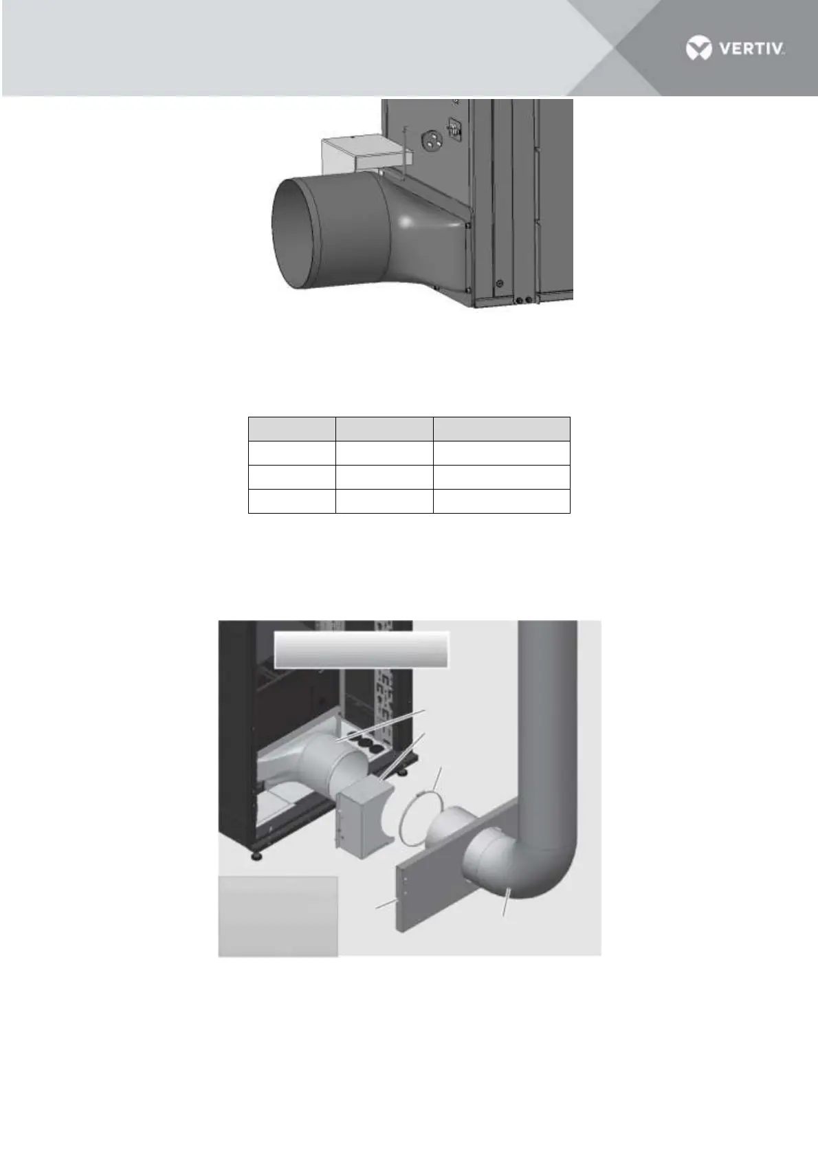
3.4.6 Connect the duct to the transition part
The total length of the cylindrical part of the transition part is 100 mm (3.94’’). To ensure the connection
reliability, the minimal overlapping of duct and transition part should not be less than 90 mm (3.54’’), and
make sure the clamping force is sufficient.
Figure 3-22 Connect the duct and transition part
NOTES:
Before connecting the duct, the air duct needs to pass through the rear cabinet plinth firstly.
Rear cabinet door shown removed
for illustrative purposes.
Transition
PN : 21121507
Condensate pump
PN : 02092419
Pipe clamp
PN : 63128710
It is showed in a VRC-S
for illustrative purpose.
The thermal separation
kit and plinth are not
included in the VRC kit.
Plinth
Air duct
PN : 27140303

Table of Contents

Other manuals for Vertiv VRC100

Related product manuals