2022/04/05 13:27 5/26 SLICE-QTC Four-Channel Temperature Controller
Product Manuals - https://www.vescent.com/manuals/
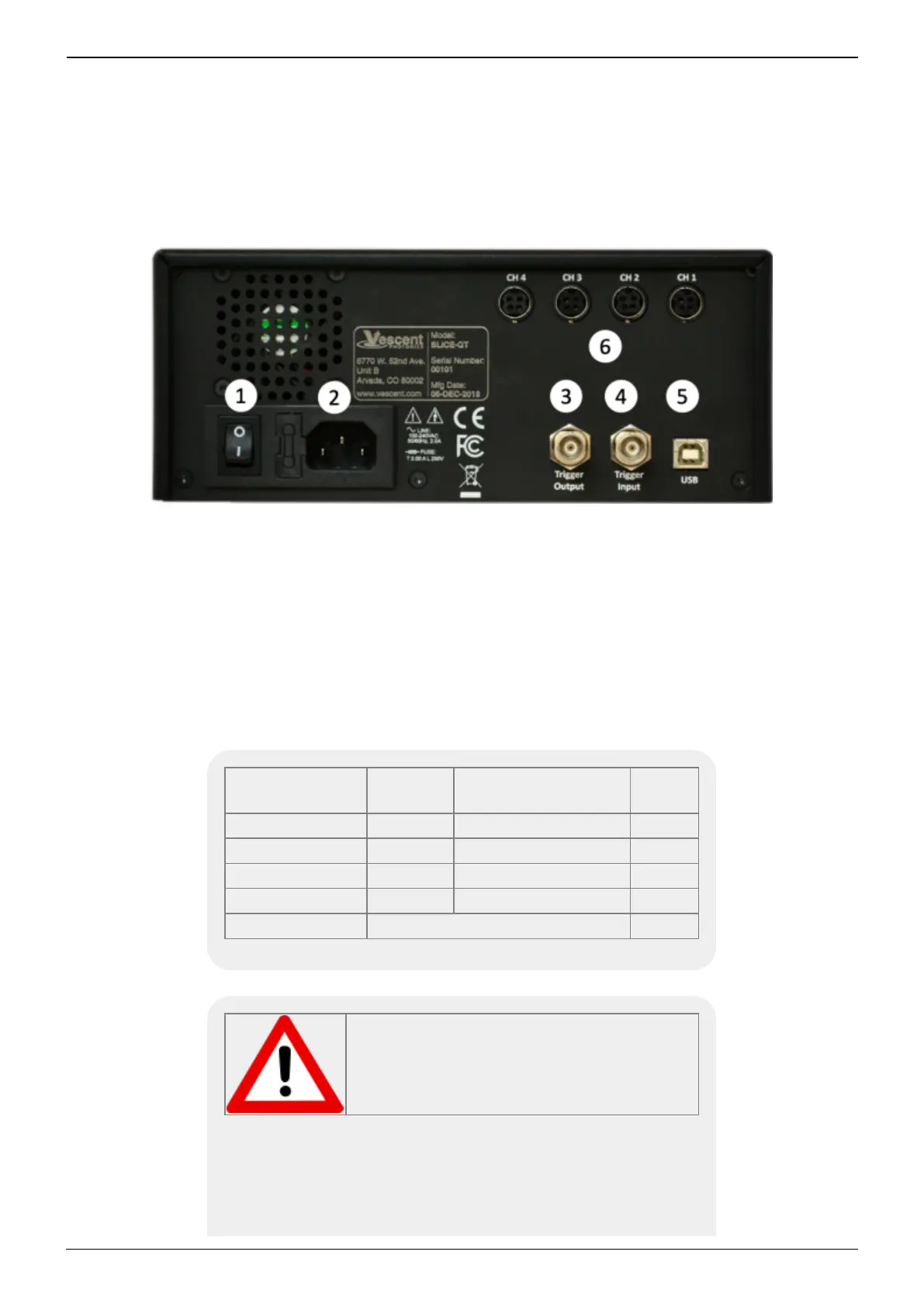
AC line power in
9)
2.
User-serviceable fuse (T 2.0 A L 250V)1.
Output trigger (BNC)3.
Input trigger (BNC)4.
USB port (Type B)5.
Connections to thermal plants
10)11)
6.
Fig. 5: View of rear of SLICE-QTC
Interface Connections
Connections to the thermal plants are made from the rear panel. Four cables for this purpose are
provided with the SLICE-QTC. Each has one end terminated with a CUI Inc. PDP-40 connector for
connecting to the CUI Inc. CP-7240-ND connector on the SLICE-QTC. The other end is unterminated
and is for connecting to your specific plant. The pin out for connecting the cable (Beldon 1502R
010500) to your specific plant is given in table 4.
Connector
Pin Number
Color Function AWG
1 Red TEC/Heater+ 18
2 Black TEC/Heater- 18
3 White Thermistor+ 22
4 Blue Thermistor- 22
Metal Sleeve Ground Shield 24
Tab. 4: Cable pinout
Do not have servo loop engaged when
connecting Servo Output to your plant.