Last update: 2022/04/01 18:06 slice:qt https://www.vescent.com/manuals/doku.php?id=slice:qt
https://www.vescent.com/manuals/ Printed on 2022/04/05 13:27
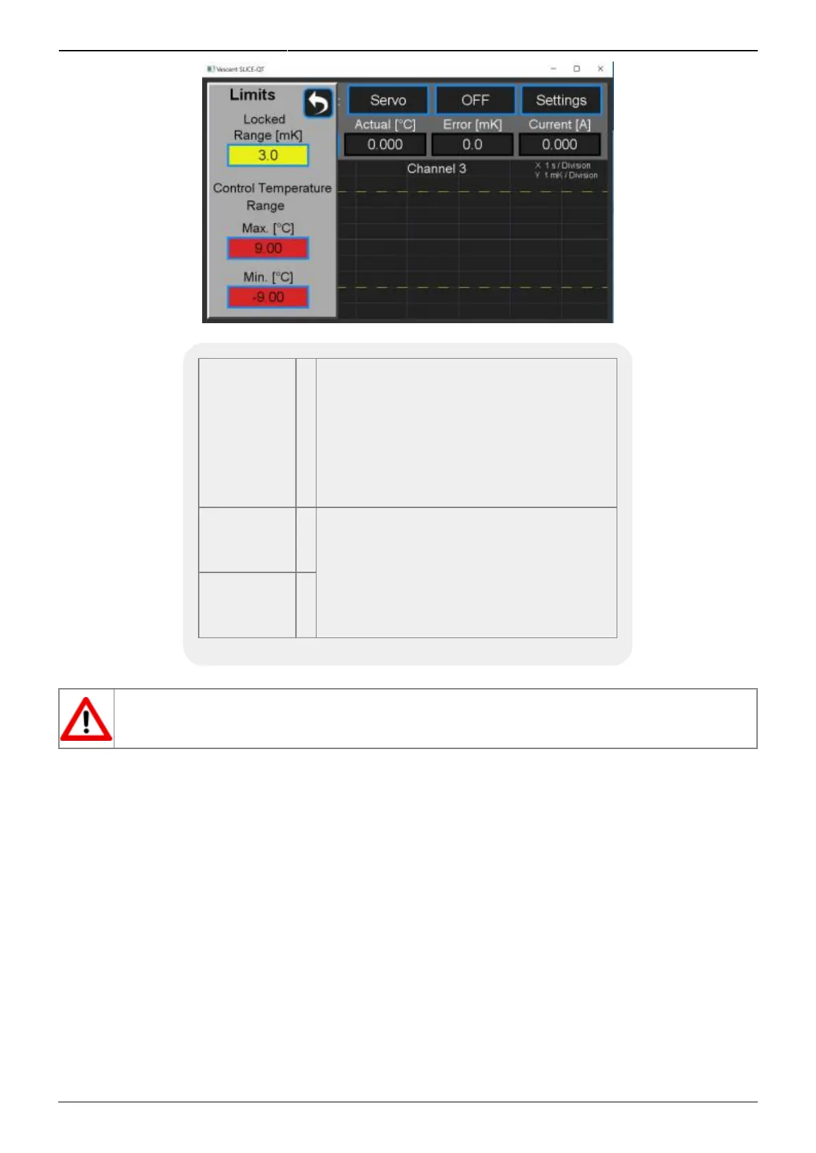
Fig. 25: Screen for setting absolute extrema and lock range
Warning
Window
ºC
Defines the nominal operating temperature
range for the plant. When the actual
temperature is within this window
(±value), the temperature error will be
displayed on a green background. When
the error in the temperature is outside this
window, the temperature error will be
displayed on a yellow background.
Maximum
Temp
ºC
Sets the maximum and minimum operating
temperatures of the plant. The user will be
prevented from adjusting the setpoint
temperature to outside this range. If the
actual temperature exceeds this range, the
temperature will be displayed on a flashing
red background.
Minimum
Temp
ºC
Tab. 6: Warning and Max/Min
If your plant is exposed to the atmosphere, use an abundance of caution in setting T
min
below
the dew point for your ambient conditions! Water will condense on surfaces that are below
the dew point temperature.
Front-panel Inputs & Outputs
The front panel of the SLICE-QTC has two analog inputs (channels A & B) and two analog outputs
(channels 1 & 2, not to be confused with the temperature control channels) available for use. The two
analog outputs can be configured to output useful monitor signals, while the two analog inputs can be
configured to provide additional functionality. A schematic of the input and output functionality is
shown in figure 26, with the light blue boxes indicating the front panel I/O. The voltage range of the
analog I/O on the SLICE-QTC is ±10 V.
To program the functionality of the front panel I/O, from any screen, touch the I/O icon on the left
sidebar. You will be presented with the screen shown in figure 27. Touch the blue-framed window to
the right of the I/O channel you wish to program. Upon doing so, you will be presented with a pull-
down menu of the various options available for that channel. For instance, if you select channel A
input, you will be presented with the screen shown in figure 28. You can select the input to be any of
the signals shown in table 7 for any of the four temperature-control channels.