This document provides installation and operation instructions for VEVOR CNC Engraving Machines, models S3020 and S4040. These machines are designed for engraving tasks, offering a balance of performance and affordability.
Function Description
The VEVOR CNC Engraving Machine is a computer numerical control (CNC) device used for precise engraving and carving on various materials. It operates by translating digital designs into physical movements of a cutting tool (spindle) across X, Y, and Z axes. The machine is controlled via software, allowing users to import G-code and execute engraving operations.
Key functions include:
- Engraving and Carving: Capable of detailed work on different materials.
- Multi-axis Control: Utilizes X, Y, and Z axes for comprehensive movement and depth control.
- Software Integration: Compatible with control software like Candle for design import, machine control, and monitoring.
- Connectivity: Features USB interface for connection to a computer and an optional offline controller for standalone operation.
- Spindle Options: Supports different spindle types (42 Spindle, 300w Spindle for S3020; 9500 RPM/Min for S4040) and laser modules.
Important Technical Specifications
The manual details two models, S3020 and S4040, with distinct specifications:
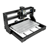
Model S3020
- Input: 110V~60Hz
- Power: 60W
- Scope of Work (Engraving Area): 300x200x60mm
- Max Engraving Speed (Main Shaft): 1200 RPM/Min
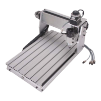
Model S4040
- Input: 110V~60Hz
- Power: 300W
- Scope of Work (Engraving Area): 400x400x75mm
- Max Engraving Speed (Main Shaft): 9500 RPM/Min
- Z-Axis Speed: 1200 RPM/Min
Common Components and Interfaces
- Control Board: Features connections for 12V Spindle, 12V Laser, X-axis, Y2, Y1, Z-axis motors, External Spindle, External Power Supply, Power on/off, 12V 5A Power Supply, USB Port, Offline Module, Water Cooling, Limit Switch (X, Y, Z), Pause, Continue, Reset, Z Zero, Reset to Factory Settings, and 12V Fan.
- Connectivity: USB interface for computer control, dedicated port for an offline controller.
- Limit Switches: Present on X, Y, and Z axes for safety and precise positioning.
- Z-probe: For automatic Z-axis height detection.
- Spindle Options: Supports 42 Spindle, 300w Spindle, and Laser modules, with specific interface connections.
Usage Features
The usage of the VEVOR CNC Engraving Machine involves several key steps, from assembly to software operation:
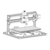
Installation Steps (Model S3020)
- Mounting Control Box: Attach the control box to the gantry frame using M5*6mm screws.
- Mounting Base: Place the gantry onto the base and secure it with M5*20mm screws.
- Interface Diagram: Connect the Z-Motor, Y-Motor, X-Motor, USB, Offline controller, Limit switches, and Z-probe to the control board as indicated. Spindle and Laser connections are also specified.
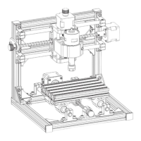
Installation Steps (Model S4040)
- Mounting Base: Assemble the base structure with the left and right Y-axis components using M5*16 screws.
- Install the Panel: Place the panel on the base, align screw holes, and secure with M5*20mm screws.
- Install the Gantry: Position the gantry frame on the left and right Y-axis and secure with M5*16 screws.
- Mounting Spindle: Place the main shaft (spindle) on the gantry frame and fix it with M5*55 screws.
- Install Y-axis Fastener: Attach two tow chain fasteners to the Y-axis using M4*6 screws.
- Install X-axis Fastener: Attach the X-axis tow chain fastener using M4*6 screws.
- Install X-axis Drag Chain Plate: Secure the X-axis drag chain plate with M4*6 screws.
- Mounting Tow Chain: Install the tow chain and secure it with M4*6 screws.
- Interface Diagram: Connect the Y2, Y1, X-axis, Z-axis motors, Laser, Set knife, Z-axis limit, Y-axis limit, Main shaft, USB Interface, X-axis limit, and Off-line handle as per the diagram.
Software Operation
- Driver Installation: Install the necessary driver (e.g., CH340SE) from the provided U disk.
- Control Software: Open the Candle control software.
- COM Port Determination: Identify the machine's COM port through Device Manager (e.g., USB-SERIAL CH340 (COMX)).
- Port and Baud Rate Selection: Select the correct COM port and baud rate (e.g., 115200) in the software.
- Connection Confirmation: Verify successful connection by observing the "Idle" status in the software.
- G-code Import: Import G-code files into the software.
- Tool Clamping: Securely clamp the tool.
- Origin Setting: Move the machine to the starting point of the code and clear the X, Y, Z origin.
- Run Code: Click "Send" to initiate the engraving process.
Maintenance Features
Matters Need Attention (Safety and General Maintenance)
- Eye Protection: Always wear protective glasses to prevent eye injury.
- Power Disconnection: Disconnect power before replacing tools, assembling/disassembling the unit, or performing maintenance.
- Unplugging: Unplug the unit when not in use or before replacing parts.
- Supervision: Close supervision is required when children are near the appliance.
- Avoid Jamming: Do not force the unit to operate under excessive pressure.
- Water Immersion: Do not immerse wires or the machine in water to prevent electric shock.
- User Competence: The appliance is not intended for use by persons with reduced physical, sensory, or mental capabilities unless supervised or instructed by a responsible person.
- Cord/Plug Damage: If the supply cord or plug is damaged, it must be replaced by the manufacturer, its service agent, or similarly qualified persons. Do not operate a damaged appliance; return it for professional service.
Fault Analysis and Countermeasures
- Engraving Machine Milling Bottom Uneven:
- Analysis: Spindle is not perpendicular to the table.
- Countermeasure: Calibrate and level the Z-axis, or use the engraving machine spindle to mill the flat plate for leveling.
- Uniaxial or Triaxial Movement is Abnormal:
- Analysis: Corresponding shaft connector is loose, or the corresponding motor wire is loose.
- Countermeasure: Tighten screws securing the shaft connector, and reinsert the motor wire.
- Offset Distance Varies When Setting the Origin:
- Analysis: Limit line is loose, or the limit switch failed.
- Countermeasure: Check if the limit line is loose, or change the limit switch.
- Engraving Misalignment:
- Analysis: Engraving speed is set too fast, or static electricity/external interference.
- Countermeasure: Slow down the carving speed. Check if the machine is grounded or if other high-power appliances are running in the circuit.