5.4.2 Installing the pneumatic hose
FIG. 12 INSTALLING THE PNEUMATIC HOSE
1. Close the external compressed air supply valve.
2. Connect the provided pneumatic hose to your
external compressed air supply system.
3. Connect the other end of the hose to the pneu-
matic connection at the connection panel of the
machine.
4. Thoroughly verify that all external pneumatic hoses
are properly seated in their corresponding con-
nections and that the hoses and connectors are
undamaged.
5. If all hoses and connectors are properly installed
and undamaged, open the external compressed air
supply valve.
5.4.3 Adjusting the air pressure with the com-
pressed air regulator
Setting the air pressure is only necessary if the air pres-
sure shown by the pressure gauge does not lie
between the minimum and maximum air pressure. You
can find specific values and additional requirements in
the chapter on technical data.
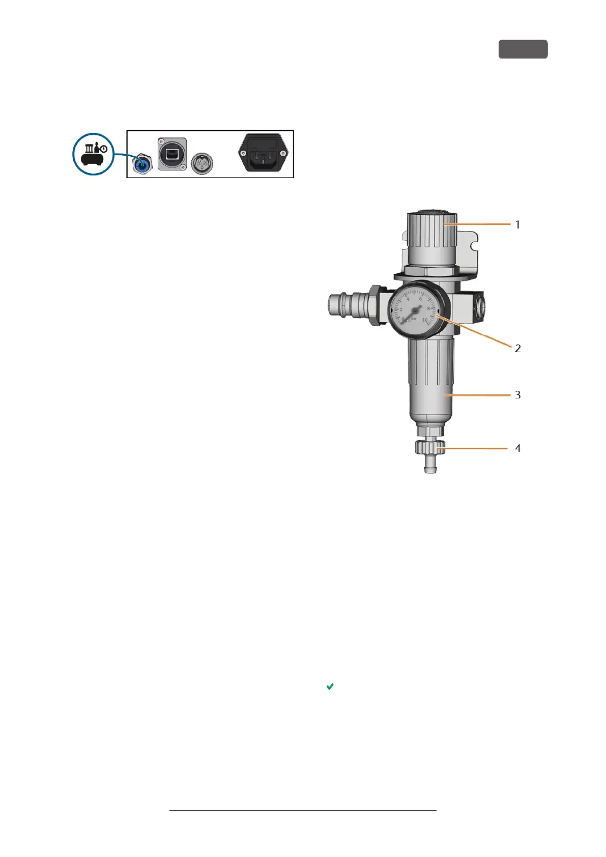
FIG. 13 COMPRESSED AIR REGULATOR: REGULATING AND MONITORING THE
AIR PRESSURE
1. Rotary knob for pressure regulation
2. Pressure gauge for monitoring the outgoing air pressure
3. Bowl of the water separator
4. Discharge screw
1. Pull the rotary knob on top of the compressed air
regulator slightly upwards.
2. Turn the rotary knob in the desired direction:
n
Turn it towards "+" to increase the pressure
n
Turn it towards "-" to decrease the pressure
3. Push the rotary knob down again.
The knob is locked and cannot be changed inad-
vertently.
R5 – Installing the machine
EN 21
Original Operating Instructions:R5
Version: 12/16/2021
 Loading...