Hardware Setup
2-9
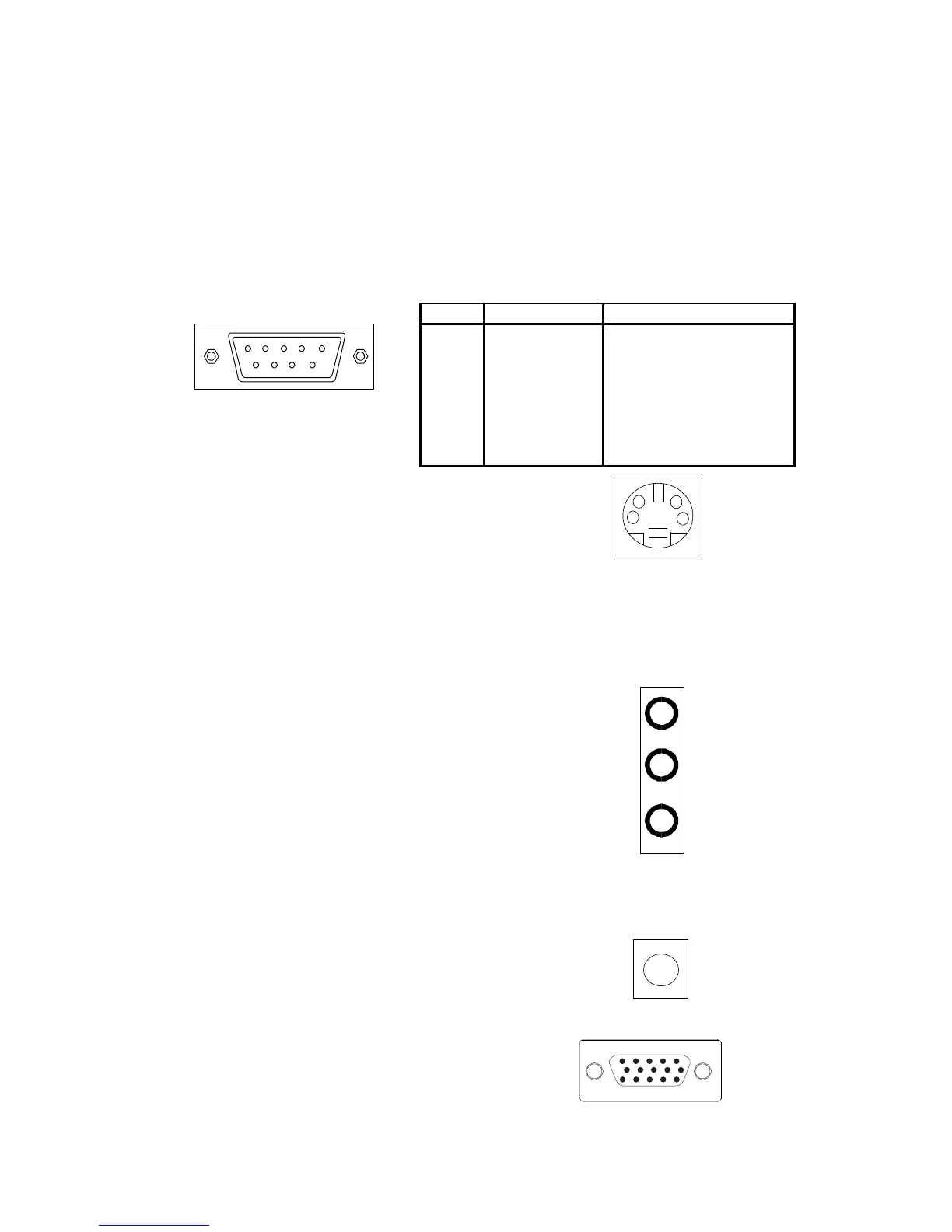
Serial Port Connectors: COM 1
The mainboard offers one 9-pin male Serial Port connector (COM 1) . You
can attach a serial mouse or other serial devices directly to this port.
S-Video Port
This port allows S-Video output in
NTSC and PAL modes.
1 2 3 4 5
6 7 8 9
9-Pin Male DIN Connectors
Audio Port Connectors
Line-Out is a connector for speakers
or headphones. The Line-In connec-
tor can be used for an external CD
player, tape player, or other audio
devices. The Mic-In connector is for
connecting microphones. Please note
when 6-channel applications are used,
all three connectors become output
connectors. Line-Out becomes Front
L/R; Line-In becomes Rear L/R; Mic-
In becomes Center/Sub. Note:
Win98SE supports only 4-CH output.
See appendix 5-1 for Smart5.1.
VGA Out
A DB-15 pin female connector that
connects to a VGA monitor.
1/8” Stereo Audio Connectors
RCA Video or S/PDIF Port
This dual function port may be used ei-
ther as a RCA Video port or as a S/
PDIF port.
(2 Channel) (6 Channel)
Line Out
MIC
Line In
L/R
Front
Rear
L/R
Sub
Center
Pin Definition
PIN SIGNAL DESCRIPTION
1 DCD Data Carry Detect
2 SIN Serial In or Receive Data
3 SOUT Serial Out or Transmit Data
4 DTR Data Terminal Ready
5. GND Ground
6. DSR Data Set Ready
7. RTS Request To Send
8. CTS Clear To Send
9. RI Ring Indicate
 Loading...