26
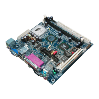
(7) Power switch: PWR BTN
This 2-pin connector connects to the case-mounted power switch to power ON/OFF the
system.
System Case Connections
PWRLED
Pin 1
SPEAK
SPKR
NC
NC
VCC5
Pin 1
JW_FP
Pin 1
HDLED
RESET
VCC5
GN D
VCC5
POWER LED
PWRBTN
PWRB TN
POWERL ED
HDDL ED
RSTS W
NC
GN D
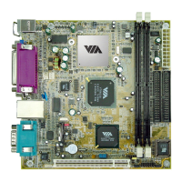
(8) FAN Headers (3-pin) : SFAN1, SFAN2, CPUFAN
These connectors support cooling fans of 350mA (4.2 Watts) or less, depending on the
fan manufacturer, the wire and plug may be different. The red wire should be positive,
while the black should be ground. Connect the fan’s plug to the board taking into
consideration the polarity of connector.
FAN Power Headers
SYSFAN2
1
3
SYSFAN1
1
3
CPUFAN
1
4
GND
+12V
CPUFAN IN
CPUFAN OUT
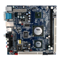
(9) CD Audio-In Headers (4-pin) : CDIN
CDIN are the connectors for CD-Audio Input signal. Please connect it to CD-ROM
CD-Audio output connector.
CD Audio-In Headers
CD IN
4 1