27
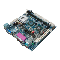
(10) IR infrared module Headers (5-pin) : IR
This connector supports the optional wireless transmitting and receiving infrared
module. You must configure the setting through the BIOS setup to use the IR function.
IR infrared module Headers
IR
Pin 1
IRTX
GND
IRRX
2
5
+5V
4
3
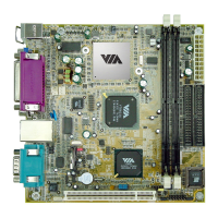
(11) Parallel Port Connector (25-pin female): PARALLEL
The On-board Parallel Port can be disabled through the BIOS SETUP. Please refer to
Chapter 3 “INTEGRATED PERIPHERALS SETUP” section for more detail
information.
Pin 1
PARALLEL Connector
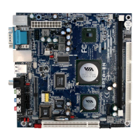
(12)
Serial COM Port: COM1
COM1 is the 9-pin block pin-header. The On-board serial port can be disabled through
BIOS SETUP. Please refer to Chapter 3 “INTEGRATED PERIPHERALS SETUP” section
for more detail information
Serial COM Port 9-pin Block
Pin1