I/,eTA
MAINTENANCE
BOTH
MODELS
CUTTING
DECKSCont.
4. Reach under culler deck with other hand , and apply pressure
to bolt and remove nut.
....
-j-Q-\-+PLUG
5. Remove blades .
6. Refit new blades in reverse order.
'\
7. Refit plug.
"
40"
·
To remove blades from right hand side culler deck follow these
procedures .
CUTTER .
DECK
1. Reach through ejector chute and locate 9/16" ring spanner onto
NUT
blade nut.
/ BEllEVillE
2. Reach under cutter deck with other hand . and apply pressure
to bolt and remove nut.
""""==::=: , -
--J
-
~
,
¥
'
''
-
"WASHER
BLADE
~
3. Remove blades .
~
I.
'R:J
BLADE
I"'=-BOLT
'f
~
~
TENSION
:r-~WASHER
4. Refit new blades in reverse order .
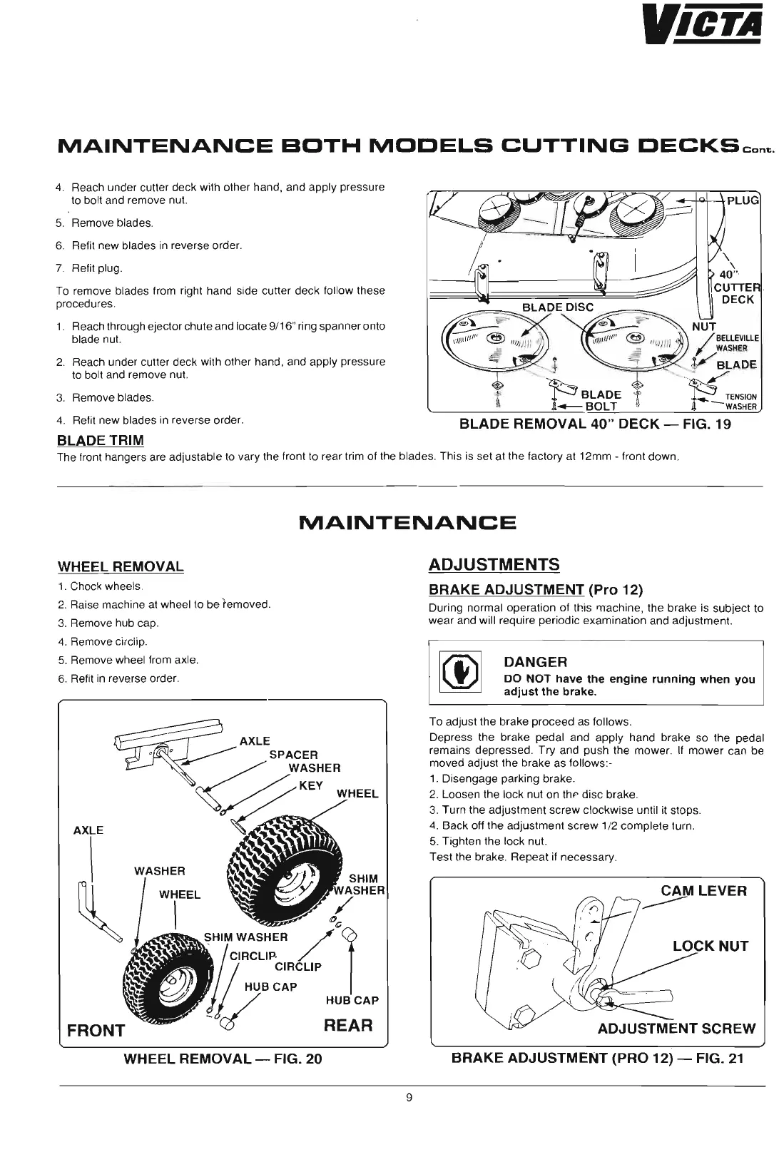
BLADE REMOVAL 40" DECK - FIG. 19
BLADE TRIM
The front hangers are adjustable to vary the front to rear trim of the blades . This is set at the factory at 12mm - front down .
WHEEL REMOVAL
1. Chock wheels .
2. Raise machine at wheel to be removed.
3. Remove hub cap.
4. Remove circlip .
5. Remove wheel from axle.
6. Refit in reverse order.
AXLE
WASHER
SHIM
ASHER
/
"c
~HIMWASHER
/ r
~
C
I
R
C
LI
P
'
~
CIRCLIP
HUBCAP
_V
HUBCAP
REAR
WHEEL REMOVAL - FIG. 20
MAINTENANCE
ADJUSTMENTS
BRAKE ADJUSTMENT (Pro 12)
During normal operation of this machine, the brake is subject to
wear and will require periodic examination and adjustment.
DANGER
DO NOT have the engine running when you
adjust the brake.
To adjust the brake proceed as follows.
Depress the brake pedal and apply hand brake so the pedal
remains depressed. Try and push the mower.
If mower can be
moved adjust the brake as follows :-
1. Disengage parking brake .
2. Loosen the lock nut on thf' disc brake.
3.
Turn the adjustment screw clockwise until it stops .
4. Back off the adjustment screw 1/2 complete turn .
5. Tighten the lock nut.
Test the brake . Repeat if necessary.
BRAKE ADJUSTMENT (PRO 12) - FIG. 21
9
 Loading...