IIleTA
MAINTENANCE
Cont.
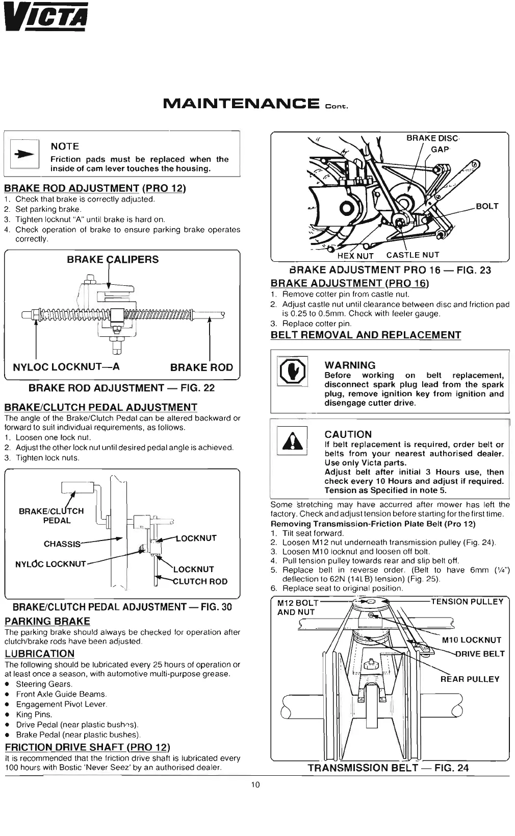
NOTE
Friction pads must be replaced when the
inside of cam lever touches the housing.
BRAKE ROD ADJUSTMENT (PRO 12)
1. Check that brake is correctly adjusted.
2. Set park ing brake .
3. Tighten locknut "A" until brake is hard on.
4. Check operat ion of brake to ensure parking brake operates
correctly.
NYLOC
LOCKNUT-A
BRAKE ROD
BRAKE ROD ADJUSTMENT - FIG.
22
BRAKE/CLUTCH PEDAL ADJUSTMENT
The angle of the Brake/Clutch Pedal can be altered backward or
forward to suit individual requirements , as follows.
1. Loosen one lock nut.
2. Adjust the other lock nut until desired pedal angle is achieved.
3. Tighten lock nuts.
BRAKE/CL TCH
PEDAL
CHASSIS
NYLdc
LOCKNUT
-
~
.
1
~
O
C
K
N U T
I
J~
I
~LOCKNUT
IhLUTCHROD
BRAKE
/CLUTCH
PEDAL
ADJUSTMENT
- FIG. 30
PARKING BRAKE
The parking brake should always be checked for operation after
clutch/brake rods have been adjusted.
LUBRICATION
The following should be lubricated every 25
hour
s of operation or
at least once a season, with automotive multi-purpose
grease
.
• Steering Gears .
• Front Axle Guide Beams.
• Engagement Pivot Lever.
• King Pins.
• Drive Pedal (near plasti c bush os),
• Brake Pedal (near plasti c bushes).
FRICTION DRIVE SHAFT (PRO 12)
It is recommended that the friction drive shaft is lubricated every
100 hours with Bostic 'Never Seez ' by an authorised dea ler.
BRAKE ADJUSTMENT PRO 16 - FIG. 23
BRAKE ADJUSTMENT (PRO 16)
1. Remove cotter pin from cas tle nut.
2. Adjust castle nut until clearance between disc and friction pad
is 0.25 to
0.5mm
.
Check
with feeler gauge .
3. Replace cotter pin.
BELT
REMOVAL
AND
REPLACEMENT
m
WARNING
Before
working
on belt replacement,
disconnect spark plug lead from the spark
plug, remove ignition key from ignition and
disengage cutter drive.
CAUTION
If belt replacement is required, order belt or
~
belts from your nearest authorised dealer.
Use only Victa parts .
Adjust belt after initial 3 Hours use, then
check every 10 Hours and adjust if required.
Tension as Specified in note 5.
Some
stretching may have accurred after
mower
has left the
factory.
Check
and adjust tension before sta rting for the first time.
Removing Transmission-Friction Plate Belt (Pro 12)
1. Tilt seat forward.
2. Loosen M12 nut underneath tran smission pulley (Fig. 24).
3. Loos en M10 locknut and loosen off bolt.
4. Pull tension pulley towards rear and slip belt off.
5. Repla ce belt in reverse order. (Belt to have 6mm ('14')
deflection to 62N (14LB) tension) (Fig. 25).
6. Replace seat to original position.
~~==~~jp'j"j'j'""i'FV1
TENSION PULLEY
<,
REAR PULLEY
-
TRANSMISSION BELT - FIG. 24
10
 Loading...