I-769N.Preaction/AC-ELEC / Victaulic
®
Series 769N FireLock NXT
™
/ Installation, Maintenance, and Testing Manual
REQUIRED INTERNAL INSPECTION
Inspect internal components at the frequency required by the current
NFPA-25 code or LPCB/EN guidelines. The authority having jurisdiction
in the area may require these inspections on a more frequent basis.
Verify these requirements by contacting the authority having jurisdiction
in the affected area.
1. Notify the authority having jurisdiction, remote station alarm
monitors, and those in the affected area that the system is being
taken out of service.
2. Open the water supply main drain valve fully to flush the water
supply of any contaminants.
3. Close the water supply main drain valve.
4. Close the water supply main control valve to take the system out of
service.
5. Open the water supply main drain valve.
6. Confirm that water is not flowing from the water supply main drain
valve.
7. Close the charge line ball valve.
8. Open the system main drain valve to drain any water that has
accumulated and to release system air pressure.
NOTE: If the system has operated, open the remote system test
valve (inspector’s test connection) and any auxiliary drain valves.
9. Close the slow-fill ball valve on the AMTA.
10. Open the manual pull station valve.
10a. ACTIVATE THE ELECTRICAL PORTION OF THE SYSTEM TO
ENERGIZE THE SOLENOIDS, OR PUSH DOWN ON THE AUTO
DRAIN SCREW TO REMOVE PRESSURE IN THE CHARGE LINE.
VERIFY THAT THERE IS NO PRESSURE ON THE GAUGES.
WARNING
• Ensure that the valve is depressurized and drained completely
before the cover plate bolts are removed.
Failure to follow this instruction could result in death or serious
personal injury and property damage.
11. After all pressure is released from the system, loosen the cover
plate bolts slowly. NOTE: DO NOT remove any cover plate bolts
until all cover plate bolts are loosened.
12. Remove all cover plate bolts, along with the cover plate and cover
plate gasket. NOTE: The 1 ½-inch/48.3-mm and 2-inch/60.3-mm
valve sizes contain washers under the heads of the cover plate
bolts. Keep these washers for re-installation.
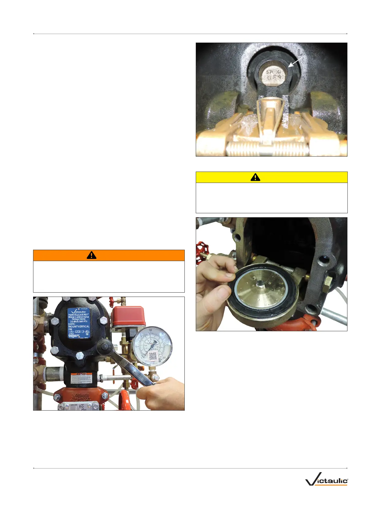
Latch
13. Push the latch back (toward the diaphragm).
CAUTION
• DO NOT use solvents or abrasives on or near the valve body seat
ring.
Failure to follow this instruction could prevent the clapper from
sealing, resulting in valve leakage.
14. Rotate the clapper out of the valve body. Inspect the clapper seal
and seal-retaining ring. Wipe away any contaminants, dirt, and
mineral deposits. Clean out any holes that are plugged in the
valve-body seat ring. DO NOT USE SOLVENTS OR ABRASIVES.
15. While the clapper is rotated out of the valve body, pull the latch
forward to inspect the diaphragm. If the diaphragm shows any
signs of wear or damage, replace it with a new, Victaulic-supplied
diaphragm. Refer to the “Removing and Replacing the Diaphragm”
section.
16. Inspect the clapper for freedom of movement and physical
damage. Replace any damaged or worn parts by following the
applicable instructions in Section VI.
17. Re-install the cover plate by following the “Installing the Cover
Plate Gasket and Cover Plate” section.
18. Place the system back in service by following the “Resetting the
System” section.
I-769N.Preaction/AC-ELEC_29REV_A
 Loading...


