Series 756 FireLock
®
European Dry Valve Stations
12
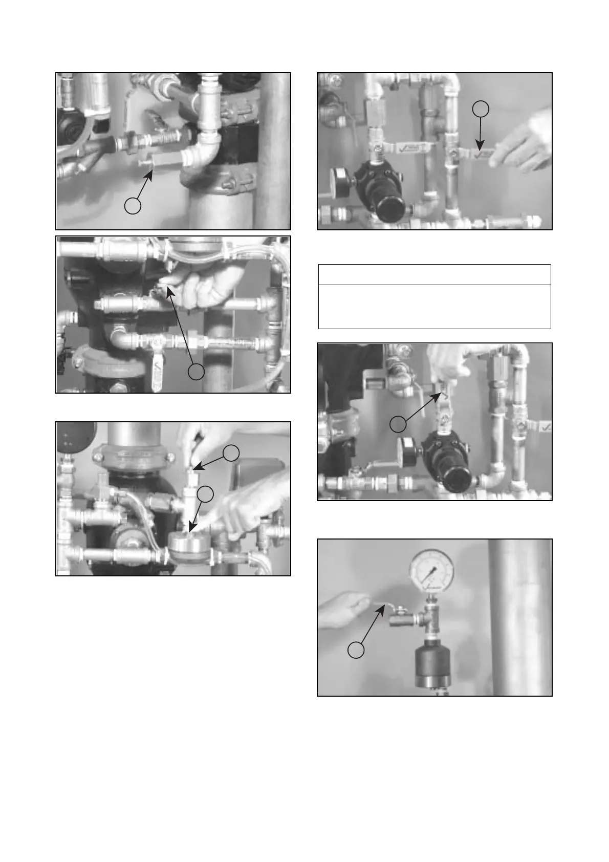
7b. If air is leaking out of the restricted orifice/alarm line drain
(19) on the alarm line, close the alarm line ball valve (17).
7c. While the system is charging, lightly push down on the
upper chamber seal of the Series 753-A Dry Actuator (23), and
pull up on the auto vent knob (13) simultaneously.
7d. When system air pressure is established, close the fast-fill
ball valve on the air maintenance device (28).
8. Open the slow-fill ball valve on the air maintenance device
(28). Confirm that the air regulator is set to the proper system
pressure.
9. If a Series 746 Dry Accelerator is used, open the
1
/
4
-turn
vent ball valve on the accelerator (14), as shown above.
19
17
23
13
NOTICE
• The Victaulic air regulator is a relief-type design.
•Any pressure in the system that is above the set point will be released.
Therefore, charging the regulator above the set point could cause prema-
ture operation of a valve installed with a Series 746 Dry Accelerator.
28
28
14
 Loading...


