EasyManuals Logo

Victaulic FireLock 756 Series Installation, Maintenance, & Testing Manual

Default Icon
30 pages
To Next Page IconTo Next Page
To Previous Page IconTo Previous Page
Page #6 background imageLoading...
Page #6 background image
Series 756 FireLock
®
European Dry Valve Stations
5
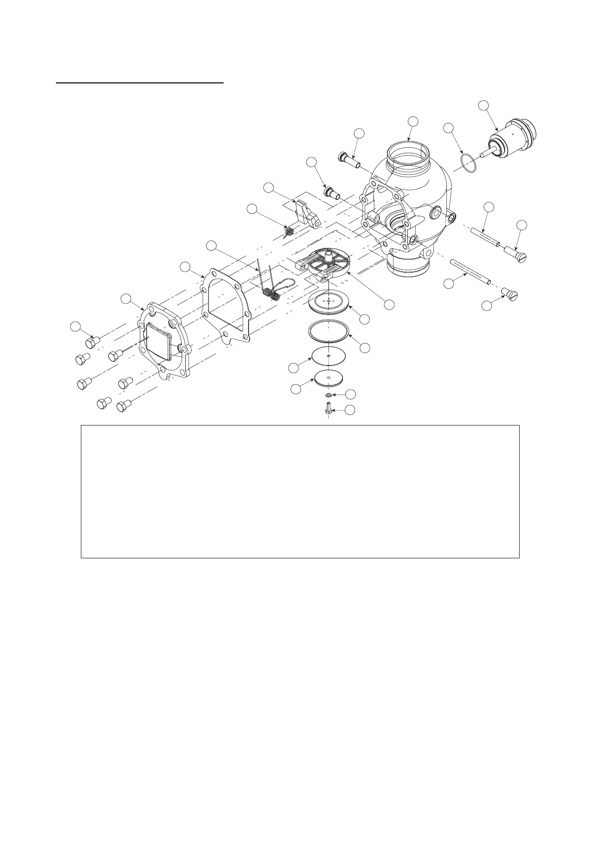
EXPLODED VIEW DRAWING – INTERNAL VALVE COMPONENTS
BILL OF MATERIALS
1 Valve Body 11 Clapper Shaft Retaining Bushing (Qty. 2)
2 Clapper 12 Latch Shaft
3 Clapper Seal 13 Latch Shaft Retaining Bushing (Qty. 2)
4 Seal Ring 14 Piston O-Ring
5 Seal Washer 15 Piston
6 Seal-Retaining Ring 16 Cover Plate Gasket
7 Bolt Seal 17 Cover Plate
8 Seal Assembly Bolt 18 Cover Plate Bolt (Qty. 7)
9 Clapper Spring 19 Latch
10 Clapper Shaft 20 Latch Spring
1
18
17
2
12
13
13
16
9
20
19
6
5
4
3
10
11
14
11
15
8
7

Other manuals for Victaulic FireLock 756 Series

Questions and Answers:

Question and Answer IconNeed help?

Do you have a question about the Victaulic FireLock 756 Series and is the answer not in the manual?

Victaulic FireLock 756 Series Specifications

General IconGeneral
BrandVictaulic
ModelFireLock 756 Series
CategoryControl Unit
LanguageEnglish

Related product manuals