Series 756 FireLock
®
European Dry Valve Stations
3
INTRODUCTION
The following instructions are a guide for proper installation of Victaulic Series 756 Dry Valves. These instructions involve pipe that is
properly prepared and grooved in accordance with current Victaulic specifications.
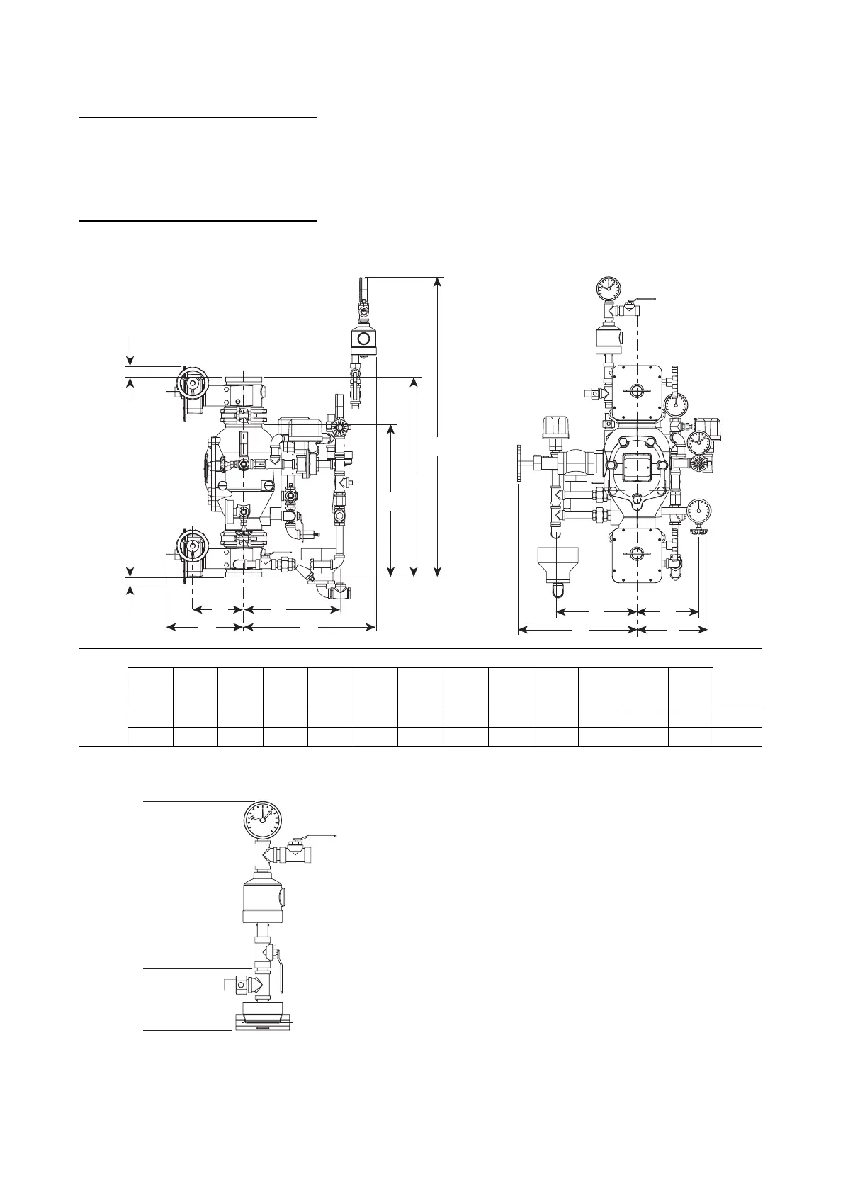
TRIM DIMENSIONS
NOTE:
An optional Series 746 Dry Accelerator adds approxi-
mately 46 cm onto the top of the Series 753-A Dry Actuator.
Valve
Size
Dimensions – centimeters Approx.
Weight
Each
kgAA
1
* BCDEFGH I JKL
DN100 50,66 63,12 94,00 16,13 30,53 31,00 41,00 8,00 19,50 28,00 43,00 25,64 10,00 67,0
DN150 56,32 71,99 94,00 18,60 34,40 33,00 46,00 – 15,19 23,00 46,00 20,50 10,00 80,0
* The A
1
dimension applies only to a valve with the additional Series 705W Butterfly Valve (optional) installed.
E
F
C D
HK
A
1
A
B
J I
G
L
Series 746
Dry Accelerator
Assembly
Series 753-A
Dry Actuator
 Loading...


