Series 756 FireLock
®
European Dry Valve Stations
7
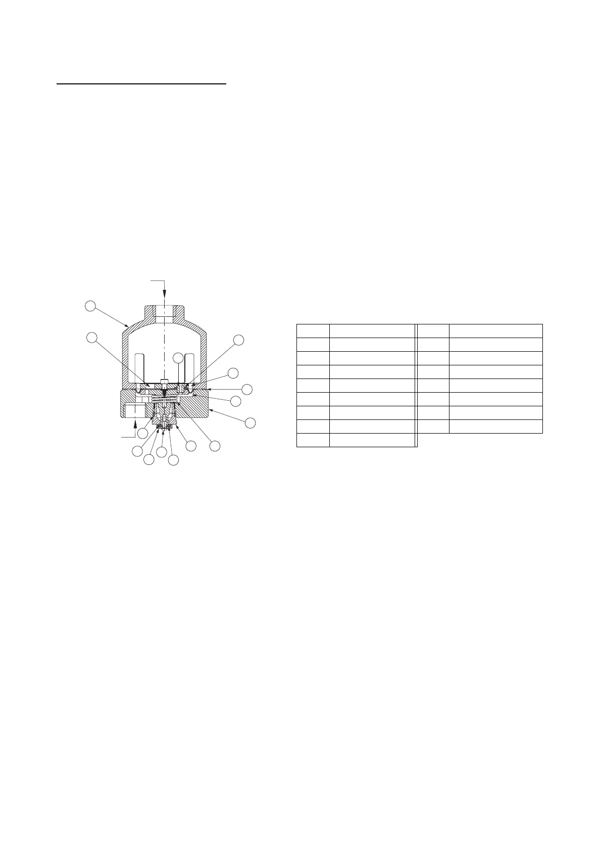
SECTION VIEW DRAWING AND DESCRIPTION – SERIES 746 DRY ACCELERATOR
The Series 746 Dry Accelerator exhausts air from the actuator to speed the operation of the valve.
A diaphragm separates the Series 746 Dry Accelerator into two chambers. The closing chamber contains a compression spring, which
maintains this chamber in the closed position. This closed position is maintained as long as the pressure differential between the opening
and closing chambers is less than 0,2 Bar.
When the system introduces air pressure into the dry accelerator, the air goes into the closing chamber and passes through a built-in
check valve to the opening chamber. The built-in check valve, which allows flow into the opening chamber, prevents pressure from
escaping the opening chamber. Therefore, air can escape only through the restrictor.
When a rapid loss of system air pressure occurs, such as an open sprinkler, air escapes from the closing chamber faster than it does
from the opening chamber. As the sprinkler system’s pressure continues to decay, a differential pressure develops across the dia-
phragm. When this differential pressure reaches 0,2 – 0,3 Bar, the opening chamber’s pressure overcomes the compression spring’s
closing force, causing the closing chamber to open to the atmosphere. The closing chamber opens immediately and releases pressure
from the actuator, resulting in valve operation.
When a slow loss of system air pressure occurs, the restrictor will compensate for up to 0,7 Bar of leakage per hour.
To Pressure
Gauge
Air Inlet from
Actuator
14
13
12
11
10
9
8
7
3
6
5
4
1
15
2
BILL OF MATERIALS
Item Description Item Description
1 Opening Chamber 9 O-ring
2 Restrictor 10 Seal Support
3 Piston 11 Closing Chamber Seal
4 O-ring 12 Button Head Cap Screw
5 Diaphragm 13 Washer
6 Actuator Shaft 14 Adjustable Seat
7 Closing Chamber 15 Built-In Check Valve
8 Compression Spring
 Loading...


