Series 756 FireLock
®
European Dry Valve Stations
14
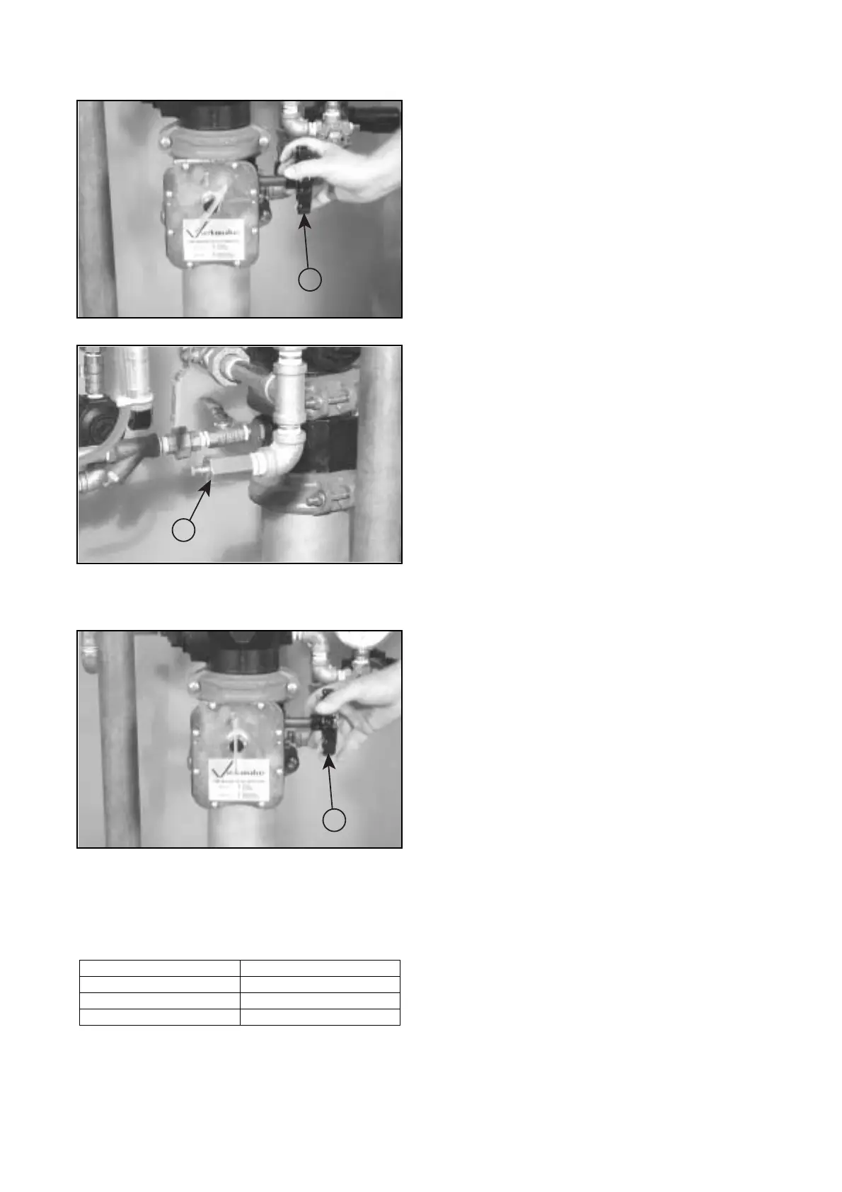
15. Open the water supply’s main control valve (2) slowly.
16. Confirm that there is no leakage from the restricted orifice/
alarm line drain (19) located in the alarm line’s piping. If water is
flowing from the restricted orifice/alarm line drain (19), close the
water supply’s main control valve (2), and start over at step 1.
17. Open the water supply’s main control valve (2) fully.
18. Record the system air pressure (7), water supply pressure
(5), and piston charge line pressure (11).
19. Ensure all valves are in their normal operating positions
(refer to table below).
20. Notify the authority having jurisdiction, remote station
alarm monitors, and those in the affected area that the system is
in service.
Valve Normal Operating Position
Piston Charge Line Ball Valve Open (Lockable)
Alarm Line Ball Valve Open (Lockable)
Alarm Test Ball Valve Closed
2
19
2
 Loading...


