Series 756 FireLock
®
European Dry Valve Stations
18
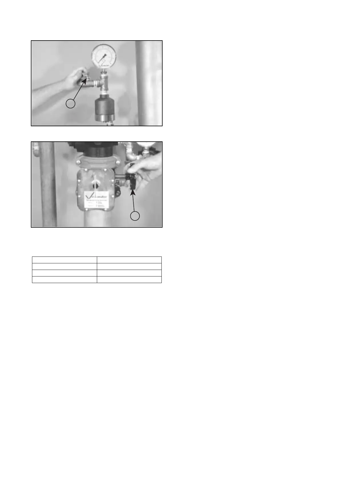
10b. Close the
1
/
4
-turn vent ball valve on the Series 746 Dry
Accelerator (14). This will set the accelerator.
11. Open the water supply’s main control valve (2).
12. Confirm that all valves are in their normal operating posi-
tions (refer to table below).
13. Notify the authority having jurisdiction, remote station
alarm monitors, and those in the affected area that the valve is
back in service.
14. Provide test results to the authority having jurisdiction, if
required.
Valve Normal Operating Position
Piston Charge Line Ball Valve Open (Lockable)
Alarm Line Ball Valve Open (Lockable)
Alarm Test Ball Valve Closed
14
2
 Loading...


