CUTMASTER 102
SERVICE Manual 0-4998
5-10
2. Bring the torch to the work piece and transfer to cutting
arc.
• OK-TO-MOVEsignalispresent.(Metershows
continuity)
3. Remove jumper from the CNC connector.
• OK-TO-MOVEsignalOFF(Metershowsnocontinu-
ity)
• Gascontinuestoow
• DCLEDgoesOFF
After20secondPostowtime
• Gassolenoidcloses
• Gasowstops
If the unit has the Basic CNC Interface harness the test is
complete. If the unit does not function as stated above,
then note the symptom and proceed to Section "5.10 CNC
Interface Problems". If the unit has the Automation Inter-
face PCB installed, continue with this section.
4. Therearethree(3) ARCVOLTAGEsignalsavailable
from the J1 connector.
a) J1-9(+)toJ2-7(-)
b) 2-5(+)toJ2-6(-)(AutoInterfacePCB4connector
P1withnojumperinstalled)=ARCVOLTSdivided
by 16.67.
c) J2-5(+)toJ2-6(-)(AutoInterfacePCB4connec-
torP1withjumperinstalledbetweenpins1and2)
=ARCVOLTSdividedby30
d) J2-5(+)toJ2-6(-)(AutoInterfacePCB4connec-
torP1withjumperinstalledbetweenpins2and3)
=ARCVOLTSdividedby50
Measure the voltage between these points while piloting
(OpenCircuitVoltage)andwhile cutting.Thevoltages
should approximate those listed below
Open Circuit Voltage Cutting Voltage
a) 300VDC 100VDC
b) 18VDC 6VDC
c) 10VDC 3.3VDC
d) 6VDC 2VDC
This completes the CNC Interface Test. If the above are all
correct then the unit is functioning correctly. If the unit does
not function as stated, then note the symptom and proceed to
Section "5.10. CNC Interface Problems".
5.07 Main Input and Internal Power
Problems
A. Primary input line fuse blows as soon as
primary disconnect is closed.
1. Primary input cable installed incorrectly.
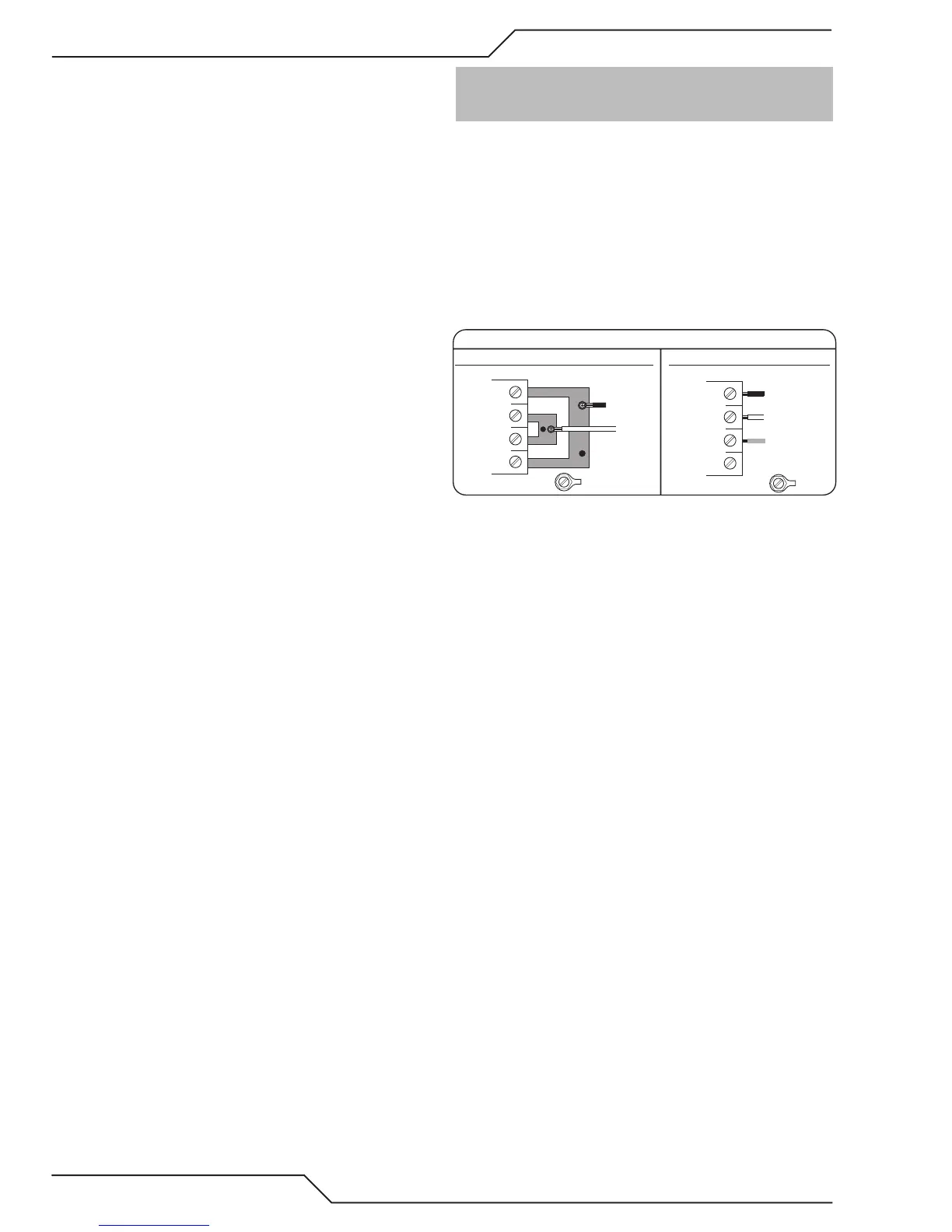
a) Checkwiringofprimarypowercabletothecontac-
tor. See illustration below.
2. W1 jumpers installed incorrectly
a) Checkjumperinstallationforcorrectphasebeing
used.
Art # A-08493
Input Power Cable Connections
Three-Phase (3ø)
Store copper jumpers on base plate
Single-Phase (1ø) and Jumper Settings
GND
L1
L2
L3
L4
GND
L1
L2
L3
L4
Single and Three Phase Input Power Wiring
3. W1 contactor points are stuck closed
a) Checkpersection5.11-A.
4. Primary plug not wired correctly.
a) Checkmanufacturer'spluginstallationinstructions.
5. Primary input cable is defective.
a) Checkcableforshorts.
B. Primary line fuses blow immediately after ON/
OFF SWITCH (SW1) is turned to ON position.
1. Shorted Input Diode Module
a) Checkpersection5.11-Band5.11-C.
2. Shorted Input Capacitor PCB 2
a) Checkpersection5.11-D.
C. Gas flows with ON/OFF SWITCH in OFF
position
1. Foreign debris has lodged in gas solenoid.
a) Replacegassolenoid.Thisisaproblemcausedby
improperlylteredairsupply.Customerneedsto
addltrationtoairsupplypriortounitinlet.
 Loading...


