Page 6 MNVCSM42A_1511_EN
3 Installation
The following procedures should be carried out before connecting to the power supply, unless indicated
otherwise.
Installation should only be carried out by skilled, authorised technicians. Incorrect connection of the
various peripherals may lead to isolation of the video switcher from the whole system.
3.1 Preliminary operations
3.1.1 Opening the package
If the package has no obvious defect due to dropping or abnormal scrapes and scratches, check the materials it
contains with the list supplied in Section 1.1 Contents of the package.
The installer technician will be responsible for disposing of the packaging material by recycling or, in any case,
according to the current legislation in the country of use.
3.1.2 Checking the markings
Before starting installation, check the identification plates to make sure the supplied material
corresponds with the required specifications, as described in Section 1.5 Identification data. Never, under any
circumstances, make any changes or connections that are not described in this manual: the use of inappropriate
devices may be very hazardous for the safety of people and the system itself.
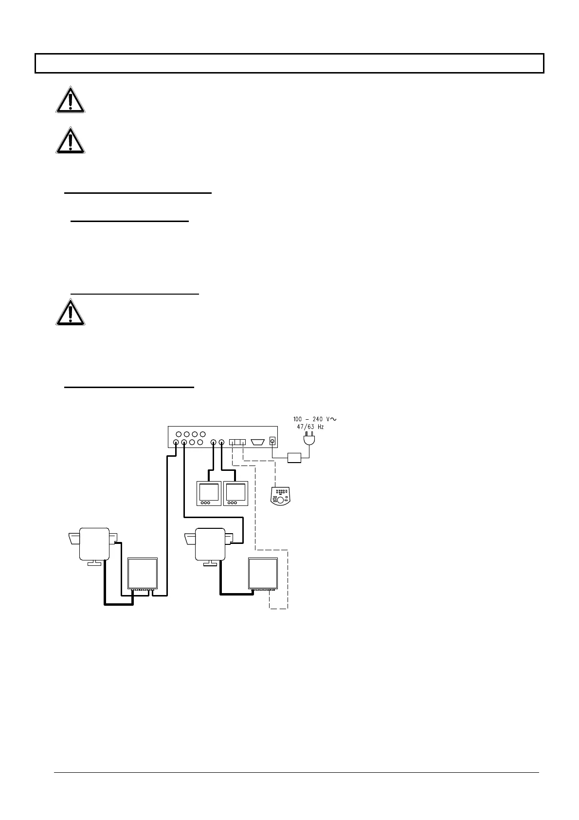
3.2 Installation example
MATERIAL USED:
Video management:
2 monitors
2 cameras
1 video matrix SM82A
Control keyboard:
1 control keyboard DCTEL
Telemetry management:
1 DTRX3 receiver with
DTCOAX board
1 receiver DTMRX1
1 pan & tilt PTH910P
1 pan & tilt PTH910
SM82A
DTRX3
DTCOA
DTMRX1
PTH910P
PTH910
DCTEL