66252090 - V1.2 - 15/03/24
- 14 -
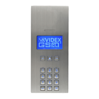
4000 Series
Art.4312 - Installation instructions
CAMERA NOTES
PRECAUTIONS ON THE CAMERA
• Please note that OPENING THE MODULE WILL INVALIDATE THE WARRANTY. In addition, any dust ingress could COM-
PROMISE THE IMAGE QUALITY.
• REMOVE THE PROTECTIVE FILM ONLY AFTER INSTALLATION AND SUCCESSFUL TESTING HAS TAKEN PLACE to avoid
scratches that could AFFECT THE IMAGE QUALITY.
MAXIMUM ILLUMINATION DISTANCE
FROM CAMERA AT NIGHT
The illumination LED’s within the camera
will illuminate the visitor when they are
within 50cm of the camera.
FIELDS OF VIEW
The elds of view is 80° for vertical angle and 170° for horizontal angle.
195 cm
80°
75 cm
135 cm
70 cm
Vertical
angle
Horizontal angle
4312
4312R
4312V
VR4312V
4312V/NFP
4312V/F
4312RV
VR4312RV
4312RV/NFP
4312RV/F
GNDV Video signal ground (coax screen and 0V to camera)
Only for video
versions
+V2 12Vdc output to supply the external camera if necessary
Max 12Vdc
150mA
VID2 Video signal input (coax centre core)
PTE “Push to exit” active low input
TRD Trade signal (from Art.701T or other devices)
BUS
BUS Connection terminals
BUS
GND
Ground
GND
NO Door open relay normally open contact 1
Max 12-24
Vac/dc 2A
C Door open relay common contact 1
+C Capacitor discharge output to supply the electric lock (when +C linked to C)
Max
12Vac/dc 2A
Not used
NC Door open relay normally closed contact 1
Max 12-24
Vac/dc 2A
Relay 1
TOP MOBILE CONNECTION TERMINAL SIGNALS
Art.4312 Audio/video digital front panel

 Loading...