66250230 - V5.0 - 31/01/21
- 2 -
4000 Series
Art.4837 - Installation instructions
Art.4837 Speaker unit for "3+1" and "4+1" systems
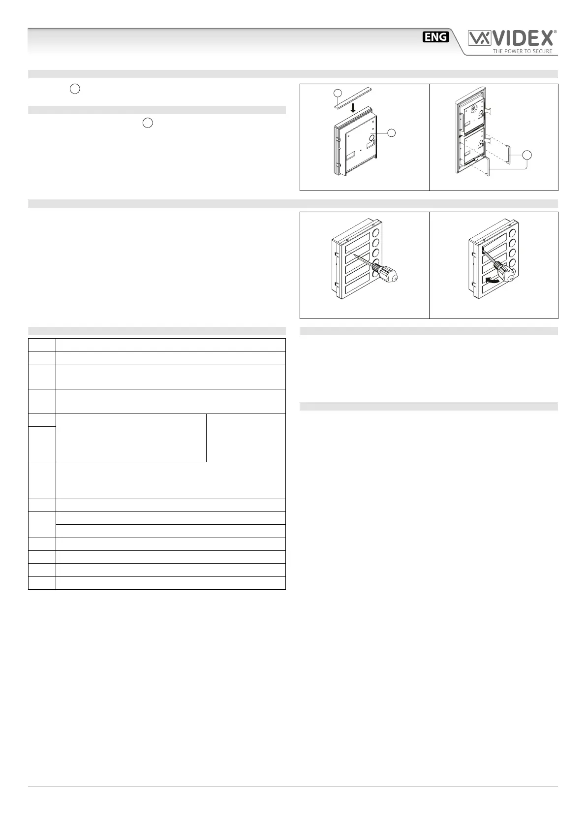
ADHESIVE GASKET PLACEMENT
Apply the
Y
seal as shown in Fig. 3.
ANTITAMPERING LOCKS FIXING
Fit the anti-tampering locks
W
as shown in Fig. 4.
Y
G
Fig. 3
W
Fig. 4
HOW TO REMOVE/INSERT THE CARD NAME HOLDER
• To avoid damage to the module front plate, mask the side that
will be in contact with the screwdriver blade;
• Insert the screwdriver (at side) into the card-holder hole as
shown in Fig. 5;
• Move the screwdriver to the left as shown in Fig. 6 to extract
the card name holder;
• Edit the card name then replace it inside the holder and ret:
insert the holder inside its housing from the left or right side
then push the other side until it clips into place.
Fig. 5 Fig. 6
CONNECTION TERMINALS SIGNALS
C Push buttons common
C1 Electronic call tone output (active only on call)
P1
Output call button 1
(available on all versions except Art.4837-0)
P2
Output call button 2
(available only on Art.4837-2)
S Normally open relay contacts (the
contact between S and S1 is closed
when the unit receives the “door
open” signal
MAX 24Vac/dc
2A
S1
RL
Active low input to enable the “door open” relay. It can
be used for a “push to exit” button or generally to com-
mand the “door open” relay
– Ground
1
Speech input
“Door Open” signal
+ 12Vdc power input for speaker unit and LED power supply
2 Speech output
P3 Output call button 3 (not used)
P4 Output call button 4 (not used)
TECHNICAL SPECIFICATION
Power Supply: +12Vdc
Power Consumption: Stand-by: Approx. 25mA
During a call: Approx. 150mA
During a conversation: Approx. 70mA
Working Temperature: -20 +60 °C
CLEANING OF THE PLATE
Use a clean and soft cloth. Use moderate warm water or non-ag-
gressive cleansers.
Do not use:
• abrasive liquids;
• chlorine-based liquids;
• metal cleaning products.

 Loading...