66250457-EN - V5.1 - 31/08/20
- 2 -
VK4K/6256 Series “6 wire Bus” videokit
VK4K/6256 Series - Installation handbook
Index
Introduction .................................................................................................................................................................................... 2
System components and available versions ................................................................................................................................ 3
General directions for installation ................................................................................................................................................ 6
Troubleshooting guide .................................................................................................................................................................. 7
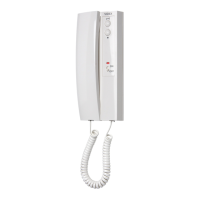
Art.4833/4833X Speaker unit ...................................................................................................................................................... 8
Art.4901 Digital codelock module .............................................................................................................................................. 14
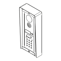
4000 Series surface and ush mounting door station installation .......................................................................................... 18
Art.6256 3.5" colour videophone .............................................................................................................................................. 20
6200 Series Videophone wall mounting instructions ............................................................................................................... 22
Art.316 - Art.316N 4 Way video distributor for system with balanced video signal ............................................................. 23
Installation diagrams ................................................................................................................................................................... 24
NOTES AND SUGGESTIONS
• All diagrams refer to all kits versions: ush or surface.
• Dashed connections refer to optional connections (“Local bell”, “Push to exit” & “Door monitor”).
• Some diagrams show how to connect a 12Vdc electric lock: these directions are suitable for all diagrams in this manual.
• Each time a setting is changed on a videophone (address, extension, number of rings etc.), the videophone must be disconnected from
the relevant connection board then after a few seconds reconnected again to allow the recognizing of the new setting.
DECLARATION OF RESPONSIBILITY
This manual has been written and revised carefully. The instructions and the descriptions which are included in it are referred to
VIDEX parts and are correct at the time of print. However, subsequent VIDEX parts and manuals, can be subject to changes without
notice. VIDEX Electronics S.p.A. cannot be held responsible for damages caused directly or indirectly by errors, omissions or discrep-
ancies between the VIDEX parts and the Manual.
WE RECOMMEND
This equipment is installed by a Competent Electrician, Security on Communications Engineer
 Loading...