NOTA IMPORTANTE
Per le connessioni Video e quelle audio, suggeriamo di utilizzare delle
coppie di fili intrecciati: una coppia per la linea video (morsetti “ ” e “ ”,
segnali “ ” e “ ”) ed una coppia per quella audio (morsetti “ ” e “ ”,
segnali “ ” ed “ ”).
2 fili da 1 mm (e 2 fili 0,35mm con l’alimentatore Art.850K/MV nel kit
VK6NMV).
fino a 50m : tutti i fili da 0.35 mm .
da 50 a 100m : fili+e-da0.75 mm ; tutti gli altri da 0.5 mm .
da 100 a 200m : fili+e-da1.5mm; tutti gli altri da 0.75 mm .
fino a 50m : fili + e - da 0.5 mm ; tutti gli altri 0.35 mm .
da 50 a 100m : fili + e - da 1 mm ; tutti gli altri 0.5 mm .
da 100 a 200m : fili + e - da 2 mm ; tutti gli altri 0.75 mm .
115
V2 V1 2 6
21
Dal trasformatore al videocitofono max 20 mt.:
Dal videocitofono al posto esterno:
per VK6N, VK6NMV, VKC6N, VKX6N
per il CVK6N
22
2
22
22
22
22
22
IMPORTANT NOTE
Video connections and Audio connections must be wired in twisted pair : pair
the video lines (terminals “ ” and “ ” signals “ ” and “ ”), pair the audio
lines (terminals “ ” and “ ” signals “ ” and “ ”).
2 wires 1 mm (plus 2 wires 0,35 mm with power supply Art.850K/MV in
VK6NMV).
up to 50 mt : all wires 0.35 mm .
from 50 to 100 mt : wires + and – 0.75 mm ; other wires 0.5 mm .
from 100 to 200 mt : wires + and – 1.5 mm ; other wires 0.75 mm
up to 50 mt : wires + and – 0.5 mm ; other cables 0.35 mm .
from 50 to 100 mt : wires + and – 1 mm ; other cables 0.5 mm .
from 100to 200 mt : wires + and – 2 mm ; other cables 0.75 mm .
115 V2V1
26 21
Between transformer and videophone 20 mt max:
Between videophone and outdoor station:
For VK6N, VK6NMV, VKC6N, VKX6N
For CVK6N
22
2
22
22
22
22
22
Tensioni di alimentazione
Assorbimento a riposo
Assorbimento massimo in funzione
Temperatura di lavoro
Videocitofono : 22-24Vac
Memory Board (solo perArt.3551) :12Vdc (+1V -4V)
Videocitofono :100mA
Memory Board (solo perArt.3551) :180mA
Videocitofono / Videophone :1,4AMax
Memory Board (solo perArt.3551) :180mA
: -10 +50 Cº
Gli Art.3351, 3451 e 3551 sono pienamente compatibili con tutti i kit VK6
prodotti fino ad oggi.
Working Voltages
Stand-by absorption
Max absorption on call
Working Temperature
Videophone :22-24Vac
Memory Board (only forArt.3551) :12Vdc (+1V -4V)
Videophone :100mA
Memory Board (only forArt.3551) :180mA
Videophone :1,4A Max
Memory Board (only forArt.3551) :180mA
: -10 +50 Cº
The videophone models 3351,3451,3551 are fully compatible with all
previous VK6 kits.
PREVIOUS VK6 KITS COMPATIBILITY
COMPATIBILITÀ CON I PRECEDENTI KIT VK6
SPECIFICHE TECNICHE TECHNICAL SPECIFICATIONS
SEZIONE DEI FILI
WIRES & SECTIONS
6
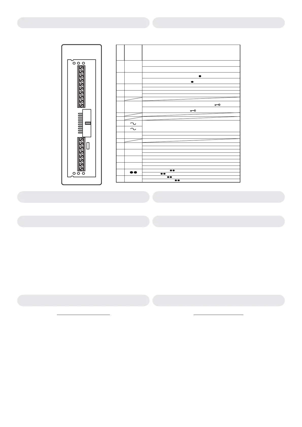
Tabella1/Table 1
PCB conn.
Art.3980
PCB conn.
provided
with
videokit
Segnali / Signals
Ingresso segnale video sinc.+.
Comando per accensione videocitofono.
1V2
Video Input +sync.
Videophone recall command.
Ingresso fonia.
Comando per autoaccensione - pulsante “
”
22
Speech input.
Camera recall output - push button “
”
Massa.
3-
Ground.
Uscita 18-30Vdc per alimentazione posto esterno.
4+
Output 18-30Vdc power supply for outdoor station.
5
Uscita fonia.
Comando per azionamento apertura porta - pulsante “
”.
61
Speech output.
Door opening output - push button “
”.
7
8
9
10
Ingresso 22-24Vac per alimentazione videocitofono
Input 22-24Vac power supply videophone.
Comando pulsante “S2”
11 S2
Push button “S2”
12
Uscita nota elettronica di chiamata per citofono o suoneria addizionali.
13 T
Output call tone for additional handset or speaker.
Ingresso +12Vdc per alimentazione memory board (solo per Art.3551).
14 +12
Input +12Vdc memory board power supply (only for Art.3551)
Ingresso segnale video sinc.-.
15 V1
Video input -sync.
Comando pulsante “S1”
16 S1
Push button “S1”
Comando pulsante “ ”.
17
Push button “ ”.
Comune pulsanti “ ”,”S1”,”S2”.
18 C
Common push buttons “ ”,”S1”,”S2”.
PCB Connection provided
with Art.3980 see Table 1
Scheda di connessione fornita
a corredo dell’Art.3980 vedi Tab.1
Fig.11
R1
*
1
2
3
4
5
6
7
8
9
10
11
12
13
14
15
16
17
18
*
Remove R1 resistor
Rimuovere la resistenza R1
La mostra i segnali dei videocitofoni Art.3351, 3451 e 3551 in
relazione ai morsetti della scheda di connessione fornita a corredo
dell’art.3980 .
Tabella 1
(fig.11)
Table 1
(Fig.11)
shows the videophones Art.3351,3451,3551 connections relevant
to the terminals of the PCB connection provided with the Art.3980 .
SEGNALI SIGNALS
X

 Loading...


