GB
General notice (liability): the details of this technical documents serve for description. Consents regarding the availability of certain features or
regarding a certain purpose always require a special written agreement.
Page 22 GB 9.2 Right reserved to make technical changes!
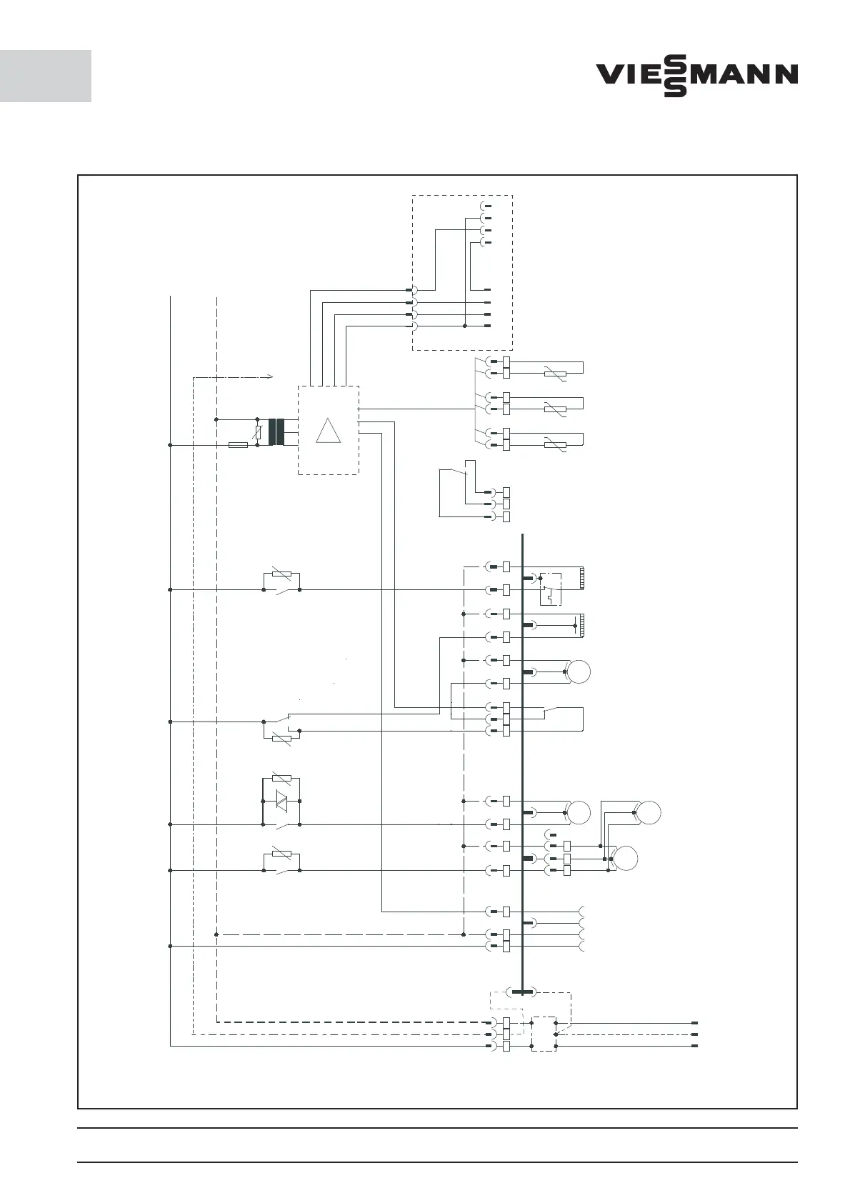
9.2 Electrical circuit diagram for
CT 0900 to CT 2000,
FT 0700 to FT 1200
GND
RF VD VF
BN
BU
BN
BU
BN
BU
E2
325
RxD
SG
SG
RxD
TxD
Connectings chematics for the optional
serial interface RS232,
included in systems supplied with
remote control
TxD
3
29
5
Romm sensor
Condenser sensor
(optional)
Evaporator
sensor
Temperature sensors
PT 1000
External fault in dicator
(in case of fault or if
without power
relay is released)
NO
NCC
A3
K4
BU
BN
BU
BN
BUBN
A2
A7
A6
BU
BK
BN
4
1
2
M 1~
BU
BNBUBN
A5
BNBUBK
A8A4A1
PE-Profile
BUPEBN
E1
Netfilter
Defrost heating
Oil heater
CompressorPressostat
BUPEBN
2
PE
3
1
M 1~
M 1~
M 1~
Evapotatorfan
Evaporatorfanr2
for housing size 2
Condenser fan
TKPE
NL1
23PE
1
4 -pin plug for
coldroom
Power supply plug
L1
PE
N
+12V
K2
R8
K5
R11
R9
K1 K3
R10
F2
80m A Tr
R1